Auto-tuning, Time chart – Yaskawa Matrix Converter User Manual
Page 312
Elevator and Hoist Type Applications
6-
147
Time Chart
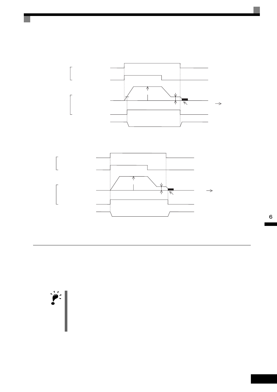
The brake on/off sequence time charts are shown in Figs. 6.84 and 6.85.
Note: For variable speed operation by an analog signal, set to b1-01 = 1.
Fig 6.84 Brake On/Off Sequence Time Chart (V/f, Open Loop Vector)
Note: For variable speed operation by an analog signal, set to b1-01 = 1.
Fig 6.85 Brake On/Off Sequence Time Chart (Flux Vector)
Auto-Tuning
Always perform Auto-Tuning with the motor before operating using vector control. Be sure to disconnect the
motor from the load before conducting Auto-Tuning. Conducting Auto-Tuning while the motor is connected
to an elevator or hoist type of application is dangerous because Auto-Tuning automatically runs the motor for
approximately one minute.
IMPORTANT
1. If the machine cannot be removed from the motor, carry out Stationary Auto-Tuning (T1-01 = 4). If Station-
ary Auto-Tuning is complete, the MxC will turn on the motor without rotating it, and automatically measures
the motor data.
2. To improve low-speed torque characteristics using V/f control, conduct Stationary Auto-Tuning for line to
line resistance only (T1-01 = 2).
3. When conducting Auto-Tuning on a wound motor or other special types of motors, obtain a test report for
the motor in advance and confirm that the E2 motor parameters after Auto-Tuning do not vary greatly from
those of the test report.
UP
S1-SC
S6-SC
off
off
d1-03
d1-01 (Enabled when b1-01 = 0)
L4-01
b4-01
off
DC Injection Braking
on
on
on
M1-M2
OPEN
CLOSE
CLOSE
Input
Output
Output frequency
0
Frequency Detection 2
(H2-01 = 05)
Time
High speed/
Low speed
Holding brake
operation
S1-SC
S6-SC
d1-01 (Enabled when b1-01 = 0)
DC Injection Braking (Zero-speed control)
M1-M2
Input
Output
Output frequency
0
During run 2
(H2-01 = 37)
Time
UP
off
off
d1-03
b2-01
off
on
on
on
OPEN
CLOSE
CLOSE
High speed/
Low speed
Holding brake
operation