Speed control (asr) structure – Yaskawa Matrix Converter User Manual
Page 280
Individual Functions
6-
115
•
When A1-02 (Control Method Selection) is set to 3 (Flux Vector Control), the Speed/Torque Change Com-
mand (a setting of 71) can be set for a multi-function input (H1-01 to H1-10) to switch between speed and
torque control during run. An example is shown below.
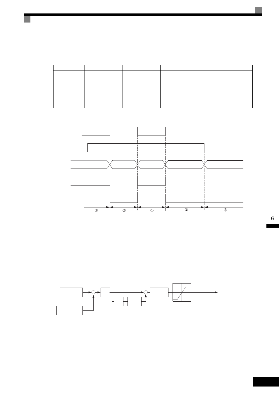
A timing chart for switching between speed and torque control is shown in the following figure.
Fig 6.69 Speed/Torque Control Switching Time Chart.
Speed Control (ASR) Structure
Speed control (ASR) during vector control adjusts the torque reference so that the deviation between the speed
reference and the estimated speed (PG feedback or speed estimator) is 0. The following block diagram shows
the structure of the speed control for vector control.
Fig 6.70 Speed Control Block Diagrams
Terminal No.
Parameter No.
Default
Setting
Function
8
H1-06
8
71
Speed/torque control change
A1
b1-01
1
1
Frequency reference selection
(terminals A1, A2)
C5-03
1
1
Speed limit (terminals A1, A2)
A3
H3-05
0
13
Torque reference/torque limit
Speed/torque change signal
(terminal S8 input)
Run Command
Control mode
Terminal A1 input
Terminal A3 input
Stop
OPEN
CLOSED
OPEN
CLOSED
Run
Speed
Torque
Speed
Torque
Speed (decel to stop)
Speed
reference
Speed limit
Speed
reference
Speed limit
Torque limit
Torque
reference
Torque limit
Torque
reference
Frequency
reference
Detected speed
Estimated speed
P
I
Torque limits
Torque reference
+
+
+
−
Speed Control Block Diagram for Vector Control
C5-01, C5-03
C5-02, C5-04
C5-06
I
limit
C5-08
Primary
filter
L7-01 to L7-04
(C5-10)