Yaskawa Matrix Converter User Manual
Page 252
Individual Functions
6-
87
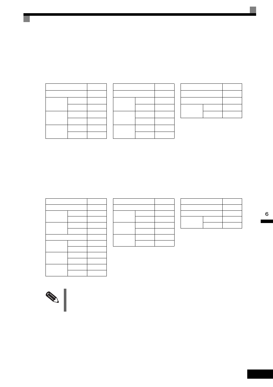
Loopback Test
The loopback test returns command messages directly as response messages without changing the contents to
check the communications between the master and slave. Set user-defined test code and data values.
The following table shows a message example when performing a loopback test with the slave 1 MxC.
Writing to Multiple Storage Registers
Write the specified data to each specified storage register from the specified addresses. The written data must
be in the following order in the command message: upper 8 bits, then lower 8 bits, in storage register address
order.
The following table shows an example of a message when forward operation has been set at a frequency refer-
ence of 60.0 Hz in the slave 1 MxC by the PLC.
Command Message
Response Message
(During Normal Operation)
Response Message
(During Error)
Slave address
01H
Slave address
01H
Slave address
01H
Function code
08H
Function code
08H
Function code
89H
Test Code
Upper bit
00H
Test Code
Upper bit
00H
Error Code
01H
Lower bit
00H
Lower bit
00H
CRC-16
Upper bit
86H
Data
Upper bit
A5H
Data
Upper bit
A5H
Lower bit
50H
Lower bit
37H
Lower bit
37H
CRC-16
Upper bit
DAH
CRC-16
Upper bit
DAH
Lower bit
8DH
Lower bit
8DH
Command Message
Response Message
(During Normal Operation)
Response Message
(During Error)
Slave Address
01H
Slave Address
01H
Slave Address
01H
Function Code
10H
Function Code
10H
Function Code
90H
Start
Address
Upper bit
00H
Start
Address
Upper bit
00H
Error code
02H
Lower bit
01H
Lower bit
01H
CRC-16
Upper bit
CDH
Quantity
Upper bit
00H
Quantity
Upper bit
00H
Lower bit
C1H
Lower bit
02H
Lower bit
02H
No. of data
04H
CRC-16
Upper bit
10H
Lead data
Upper bit
00H
Lower bit
08H
Lower bit
01H
Next data
Upper bit
02H
Lower bit
58H
CRC-16
Upper bit
63H
Lower bit
39H
INFO
Set the number of data specified using command messages as quantity of specified messages
× 2. Handle
response messages in the same way.