Wiring, Wiring the pg-b2 – Yaskawa Matrix Converter User Manual
Page 64
2
-30
Wiring
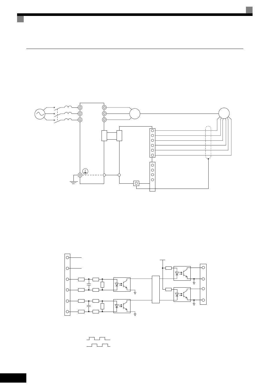
Wiring examples are provided in the following illustrations for the option cards.
Wiring the PG-B2
Wiring examples for the PG-B2 are provided in the following illustrations.
•
Shielded twisted-pair wires must be used for signal lines.
•
Do not use the pulse generator power supply for anything other than the pulse generator (encoder).
Using it for another purpose can cause malfunctions due to noise.
•
The length of the pulse generator wiring must not be more than 100 meters.
•
The direction of rotation of the PG can be set in parameter F1-05. The factory preset is Phase A leads
with a forward run command.
Fig 2.25 PG-B2 Wiring
•
When connecting to a voltage-output-type PG (encoder), select a PG that has an output impedance with
a current of at least 12 mA to the input circuit photocoupler (diode).
•
The pulse monitor dividing ratio can be changed using parameter F1-06 (PG division rate).
•
The pulse monitor emitter is connected to common inside the PG-B2. The emitter common must be used
for external circuits.
Fig 2.26 I/O Circuit Configuration of the PG-B2
Three-phase
200 VAC (400 VAC)
MxC
4CN
E
E
4CN
TA1 1
2
3
4
TA2
TA3 (E)
1
2
3
4
5
6
PG-B2
IM
PG
R/L1
S/L2
R/L3
U/T1
V/T2
W/T3
Power supply +12 V
Power supply 0 V
A-phase pulse input (+)
A-phase pulse input (-)
B-phase pulse input (+)
B-phase pulse input (-)
A-phase pulse monitor output
B-phase pulse monitor output
1
TA1
2
3
4
5
6
+12 V
0 V
150
180
150
180
470
150
180
150
180
470
1
2
3
4
TA2
PG power
supply +12 V
A-phase pulse
input
B-phase pulse
input
A-phase
pulses
B-phase
pulses
Division rate
circuit
B-phase pulse
monitor output
A-phase pulse
monitor output
A-phase pulses
B-phase pulses