Setting the v/f pattern, Related parameters – Yaskawa Matrix Converter User Manual
Page 269
6
-104
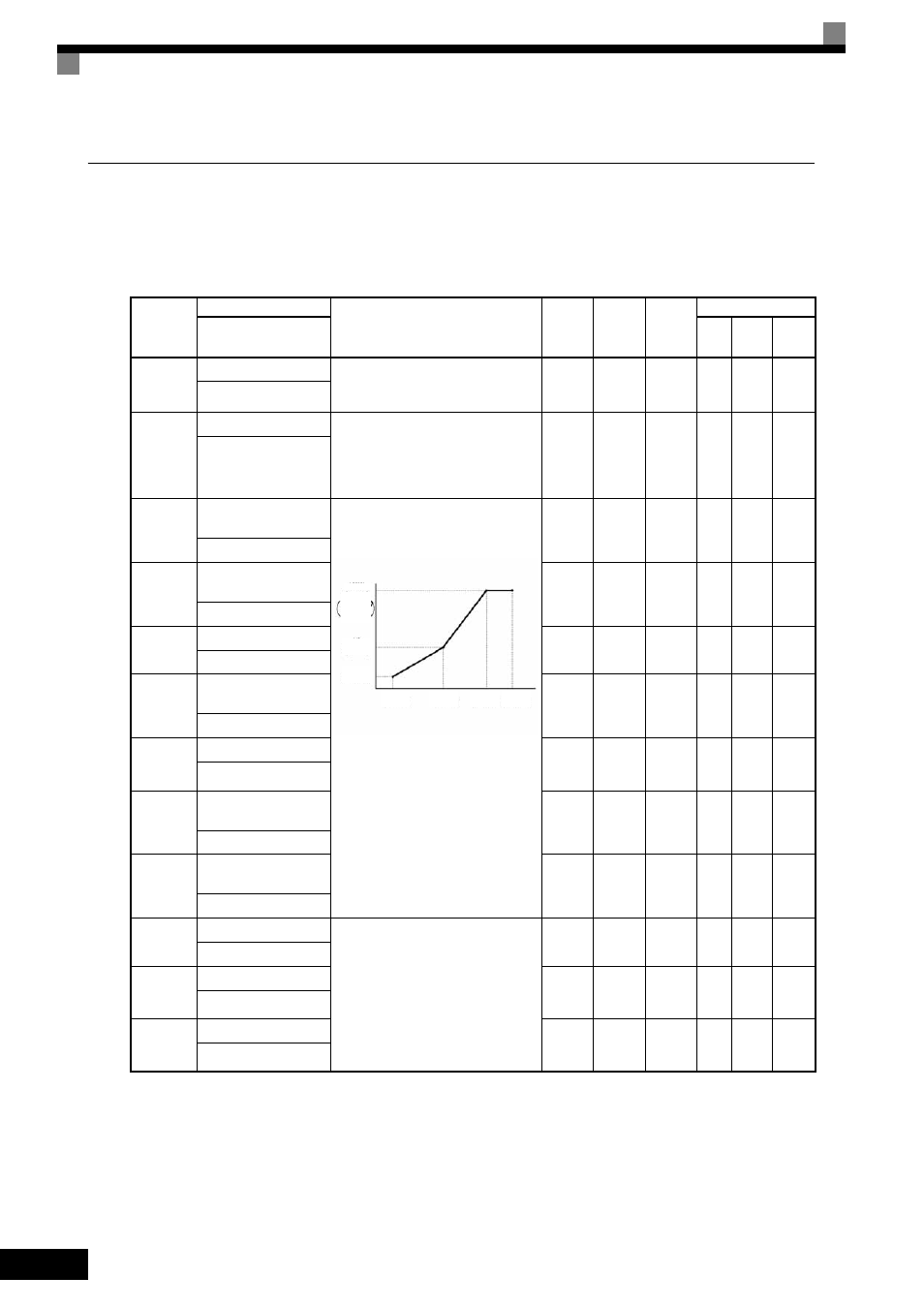
Setting the V/f Pattern
In V/f Control Method, the MxC input voltage and the V/f pattern can be set as the need arises.
Related Parameters
* 1. Values appearing in this table are for a 200 V class MxC. Double values when using a 400 V class MxC.
* 2. The default will change when the control method is changed. The Open Loop Vector defaults are given.
* 3. E1-11 and E1-12 are disregarded when set to 0.0.
* 4. E1-13 is set to the same value as E1-05 by Auto-Tuning.
Parameter
Number
Name
Description
Setting
Range
Default
Change
during
Run
Control Methods
Display
V/f
Open
Loop
Vector
Flux
Vector
E1-01
Input Voltage Setting
Set the MxC input voltage in 1 volt.
This setting is used as a reference value
in protection functions.
155 to
255
*1
200
VAC
*1
No
Q
Q
Q
Input Voltage
E1-03
V/f Pattern Selection
0 to D: Select from the 14 preset pat-
terns.
F:
Custom user-set patterns
(Applicable for settings E1-04
to E1-10).
0 to D,
F
F
No
Q
Q
No
V/f Selection
E1-04
Maximum Output Fre-
quency
To set V/f characteristics in a straight
line, set the same values for E1-07 and
E1-09. In this case, the setting for E1-08
will be disregarded.
Always ensure that the four frequencies
are set in the following manner:
E1-04 (FMAX)
≥ E1-06 (FA) > E1-07
(FB)
≥ E1-09 (FMIN)
40.0 to
120.0
60.0 Hz
*2
No
Q
Q
Q
Max Frequency
E1-05
Maximum Output Volt-
age
0.0 to
255.0
*1
200.0
VAC
*1 *2
No
Q
Q
Q
Max Voltage
E1-06
Base Frequency
0.0 to
120.0
60.0 Hz
*2
No
Q
Q
Q
Base Frequency
E1-07
Mid Output Frequency
A
0.0 to
120.0
3.0 Hz
*2
No
A
A
No
Mid Frequency A
E1-08
Mid Output Voltage A
0.0 to
255.0
*1
13.0
VAC
*1 *2
No
A
A
No
Mid Voltage A
E1-09
Minimum Output Fre-
quency
0.0 to
120.0
0.5 Hz
*2
No
Q
Q
A
Min Frequency
E1-10
Minimum Output Volt-
age
0.0 to
255.0
*1
2.5
VAC
*1 *2
No
A
A
No
Min Voltage
E1-11
Mid Output Frequency B
Set only to fine-adjust V/f for the output
range. Normally, this setting is not
required.
0.0 to
120.0
0.0 Hz
*3
No
A
A
A
Mid Frequency B
E1-12
Mid Output Voltage B
0.0 to
255.0
*1
0.0
VAC
*3
No
A
A
A
Mid Voltage B
E1-13
Base Voltage
0.0 to
255.0
*1
0.0
VAC
*4
No
A
Q
Q
Base Voltage
Output voltage (V)
Frequency (Hz)
FMIN
(E1-09)
FB
(E1-07)
FA
(E1-08)
FA
(E1-04)
VC
(E1-08)
VMIN
(E1-10)
(E1-05)
(V BASE)
(E1-13)
VMAX