Time chart, Application precautions – Yaskawa Matrix Converter User Manual
Page 289
6
-124
Monitor Function
Time Chart
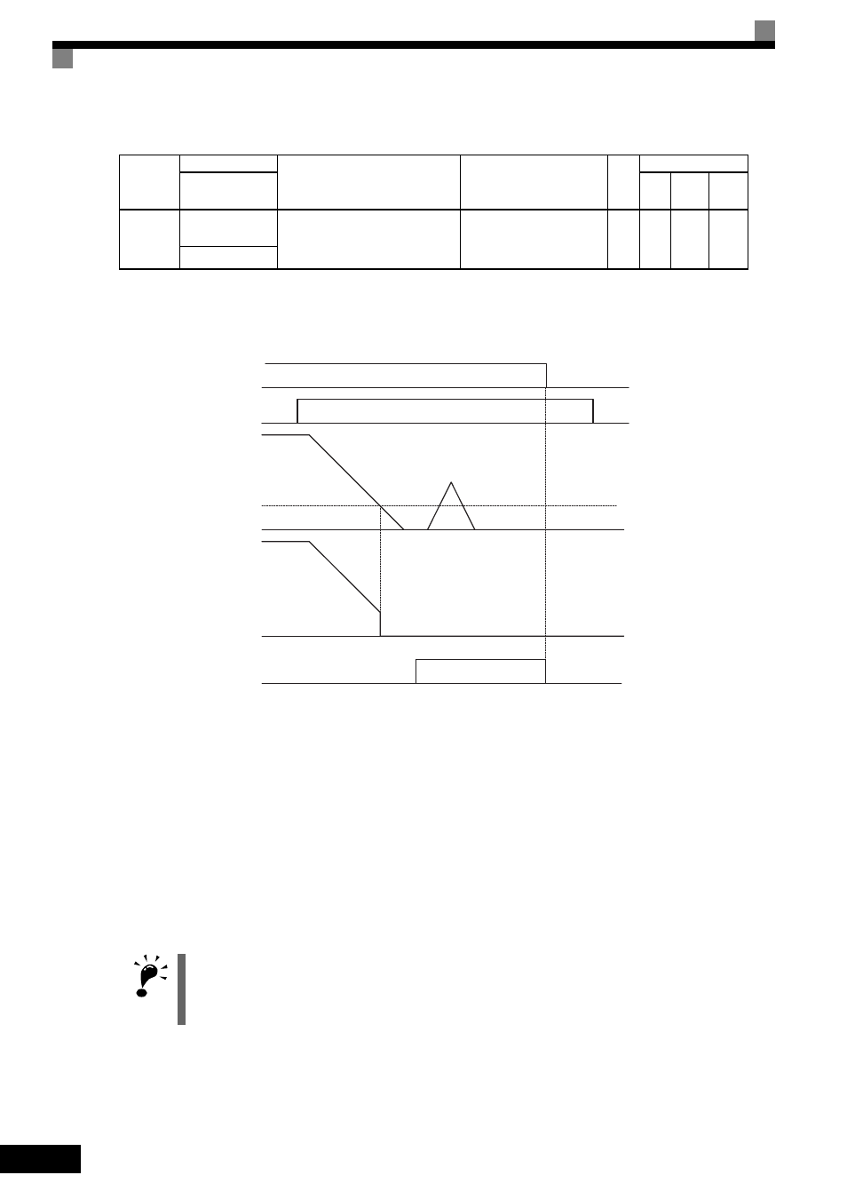
A time chart for the zero-servo function is given in Time Chart for Zero-Servo.
Fig 6.79 Time Chart for Zero-Servo
Application Precautions
•
Be sure to leave the Run Command input on. If the Run Command is turned off, the output will be inter-
rupted and the zero-servo function will be disabled.
•
The holding force of the zero-servo is adjusted in b9-01. The holding force will increase if the value of the
setting is increased, but oscillation and hunting will occur if the setting is too large. Adjust b9-01 after
adjusting the speed control gain.
•
The zero-servo detection width is set as the allowable position offset from the zero-servo start position. Set
4 times the number of pulses from the PG.
•
The Zero-servo End signal will go off when the Zero-Servo Command is turned off.
Parameter
Number
Name
Description
Output Signal Level
During Multi-Function
Analog Output
Min.
Unit
Control Methods
Display
V/f
Open
Loop
Vector
Flux
Vector
U1-35
Zero-Servo move-
ment pulses
Shows the number of PG pulses times
4 for the movement range when
stopped at zero.
No output available
1
No
No
A
Zero Servo Pulse
IMPORTANT
Do not lock the servo for extended periods of time at 100% when using the zero-servo function. MxC errors
may result. Extended periods of servo lock can be achieved by ensuring that the current during the servolock
is 70% or less or by increasing the MxC output capacity.
Run Command
on
off
Zero servo command
Frequency (speed) reference
Excitation level
b2-01
Motor speed
Zero Servo End signal
Zero-servo status
on
off