Yaskawa Matrix Converter User Manual
Page 219

6
-54
Motor Overheating Protection Using PTC Thermistor Inputs
Perform motor overheating protection using the thermistor temperature resistance characteristics of the PTC
(Positive Temperature Coefficient) built into the windings of each motor phase.
Related Parameters
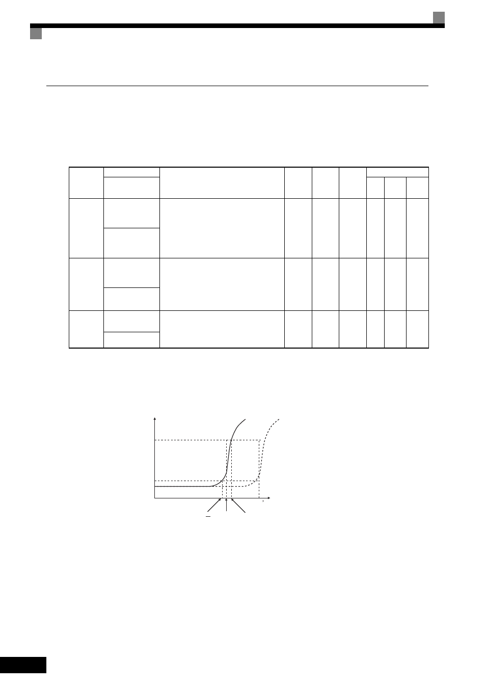
PTC Thermistor Characteristics
The following diagram shows the characteristics of the PTC thermistor temperature to the resistance value.
Fig 6.40 PTC Thermistor Temperature-Resistance Value Characteristics
Parameter
Number
Name
Description
Setting
Range
Default
Change
during
Run
Control Methods
Display
V/f
Open
Loop
Vector
Flux
Vector
L1-03
Motor Overheat
Alarm Operation
Selection
Sets operation selection when the motor tem-
perature analog input (H3-09 = E) exceeds the
OH3 alarm level (1.17V)
0: Decelerate to Stop
1: Coast to Stop
2: Fast-Stop
3: Alarm Only
0 to 3
3
No
A
A
A
Mtr OH Alarm Sel
L1-04
Motor Overheat
Fault Operation
Selection
Sets stopping method when the motor temper-
ature analog input
(H3-09 = E) exceeds the OH4 fault level.
0: Decelerate to Stop
1: Coast to Stop
2: Fast-Stop
0 to 2
1
No
A
A
A
Mtr OH Fault Sel
L1-05
Motor Temperature
Input Filter Time
This parameter adjusts the filter on the motor
temperature analog input (H3-09 = E).
Increase to add stability, decrease to improve
response.
0.00 to
10.00
0.20 s
No
A
A
A
Mtr Temp Filter
Tr: Temperature threshold value
Tr
Tr+5
Tr
Tr
5
550
1330
Resistance (ohms)
Class F
150
°C
Class H
180
°C
Temperature
