Yaskawa Matrix Converter User Manual
Page 160
5
-60
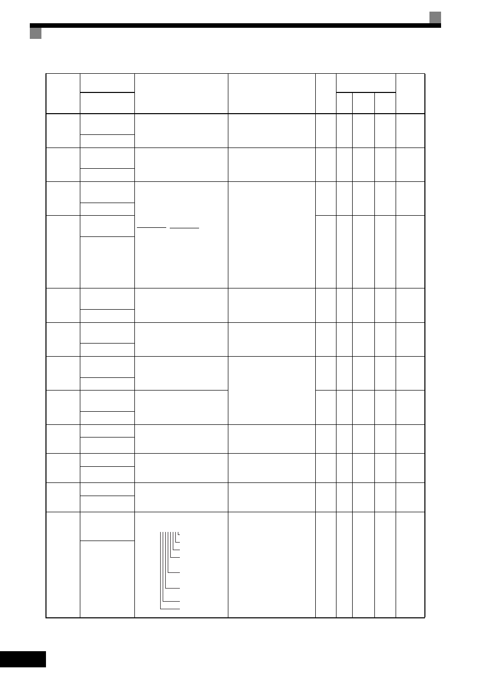
U1-27
Output voltage ref-
erence (Vd)
Monitors the MxC internal volt-
age reference for motor excitation
current control.
10 V: 200 VAC (400 VAC)
(
−10 V to + 10 V possible)
0.1
VAC
No
A
A
5AH
Voltage Ref (Vd)
U1-28
Software No.
(CPU)
(Manufacturer’s CPU software
No.)
No output available
-
A
A
A
5BH
CPU ID
U1-29
Output power
lower 4 digits
Monitors the MxC’s output
power. The display is split into
upper digits and lower digits in
the following way.
Example: If the output power is
12345678.9 kWh, the display will
be as follows:
U1-29: 678.9 kWH
U1-30: 12345 MWH
(Analog monitor: No output)
0.0 to 32767999.9
0.1
kWH
A
A
A
5CH
kWh Lower 4 dig
U1-30
Output power
upper 5 digits
MW
H
A
A
A
5DH
kWh Upper 5 dig
U1-32
ACR output of q
axis
Monitors the current control out-
put value for the motor secondary
current.
10 V: 100%
(
−10 V to + 10 V possible)
0.1
%
No
A
A
5FH
ACR(q) Output
U1-33
ACR output of d
axis
Monitors the current control out-
put value for the motor excitation
current.
10 V: 100%
(
−10 V to + 10 V possible)
0.1
%
No
A
A
60H
ACR(d) Output
U1-34
OPE fault parame-
ter
Shows the first parameter number
where an OPE fault was detected.
No output available
-
A
A
A
61H
OPE Detected
U1-35
Zero-servo move-
ment pulses
Shows the number of PG pulses
times 4 for the movement range
when stopped at zero.
1
No
No
A
62H
Zero Servo Pulse
U1-36
PID input volume
PID feedback volume
Given as maximum frequency/
100%
10 V: Max frequency
(
−10 V to + 10 V possible)
0.01
%
A
A
A
63H
PID Input
U1-37
PID output volume PID control output
Given as maximum frequency/
100%
10 V: Max frequency
(
−10 V to + 10 V possible)
0.01
%
A
A
A
64H
PID Output
U1-38
PID target value
PID target value
Given as maximum frequency/
100%
10 V: Max frequency
0.01
%
A
A
A
65H
PID Setpoint
U1-39
MEMOBUS
communications
error code
Shows MEMOBUS errors.
No output available
-
A
A
A
66H
Transmit Err
Parameter
Number
Name
Description
Output Signal Level
during Multi-Function
Analog Output
Min.
Unit
Control
Methods
MEMO-
BUS
Register
Display
V/f
Open
Loop
Vector
Flux
Vector
kWH
U1-30 U1-29
1: CRC error
1: Data length error
Not used (always 0).
1: Parity
error
1: Overrun
error
1: Framing
ޓerror
1: Timeout
Not used (always 0).
U1-39= 00000000