Connection example and time chart – Yaskawa Matrix Converter User Manual
Page 171
6
-6
Connection Example and Time Chart
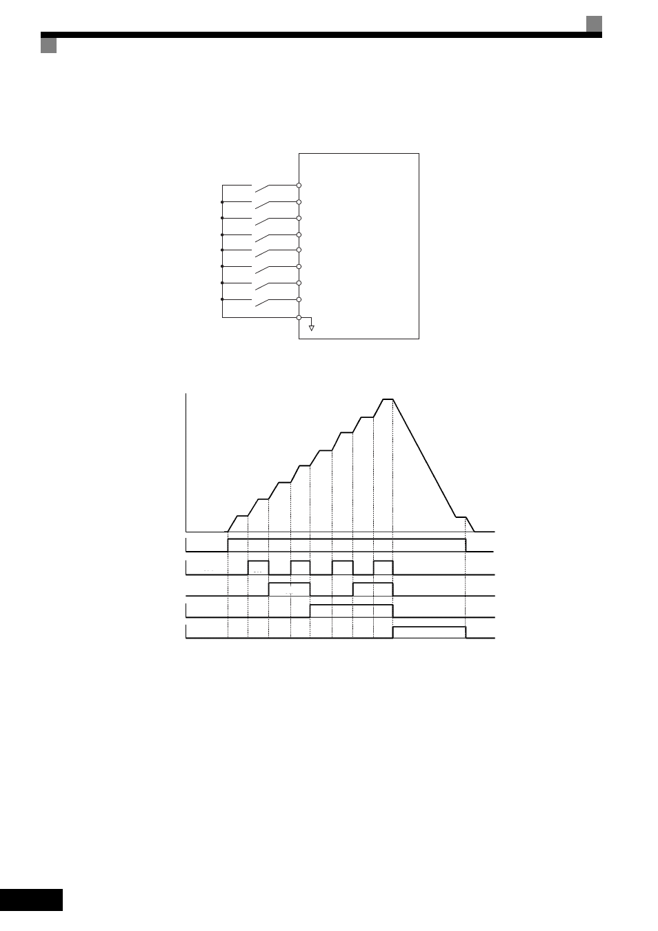
The following diagram and time chart show how to set up the control circuit terminal for a 9-step speed
sequence.
Fig 6.5 Control Circuit Terminal during 9-Step Operation
Fig 6.6 Multi-Step Speed Reference/Jog Frequency Selection Time Chart
Setting Precautions
When setting analog inputs to step 1 to step 2, observe the following precautions.
•
Step 1
When setting terminal A1’s analog input to step 2, set b1-01 to 1, and when setting d1-01 (Frequency Ref-
erence 1) to step 1, set b1-01 to 0.
•
Step 2
When setting the analog input for terminal A2 to step 2, also set H3-09 to 2 (Auxiliary Frequency Refer-
ence 1). When setting d1-02 (Frequency Reference 2) to step 2, set H3-05 to 1F (do not use analog inputs).
•
Step 3
When setting terminal A3’s analog input to step 3, set H3-05 to 3 (Auxiliary Frequency Reference 2).
When setting d1-03 (Frequency Reference 3) to step 3, set H3-05 to 1F (analog input not used).
MxC
S1 Forward/stop
S2 Reverse/stop
S3 External fault
S4 Fault reset
S5 Multi-step speed reference 1
S6 Multi-step speed reference 2
S9 Multi-step speed reference 3
SC Sequence common
S7 Jog frequency
Forward/stop
Multi-Step Speed
Reference 1
Multi-Step Speed
Reference 2
Multi-Step Speed
Reference 3
Jog Frequency
Selection
Frequency
Reference 3
Frequency
Reference 4
Frequency
Reference 5
Frequency
Reference 6
Jog Frequency
Frequency
Reference 8
Frequency
Reference 7
Frequency
Reference
Frequency Reference 1:
Master Speed
Frequency
Frequency Reference 2:
Auxiliary Speed Frequency
on
on
on
on
on
off
off
off
off
off