Yaskawa Matrix Converter User Manual
Page 309
6
-144
Selecting the Input Terminal Function for a DI-08 Digital Speed Reference Card
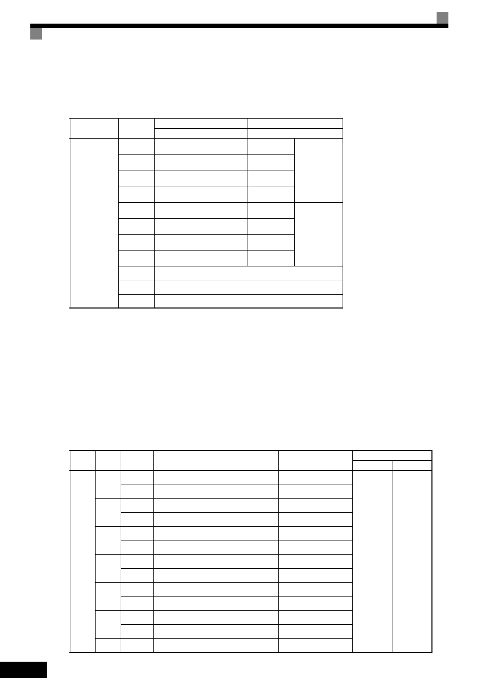
The frequency reference from a DI-08 Card is determined by the setting of F3-01, as shown in the following
table.
Application Precautions
The DI-08 will not function if F3-01 is set to 6
Selecting the Digital Reference
The range of the digital references is determined by the combination of the settings of o1-03 and F3-01. The
information monitored in U1-01 (Frequency reference) will also change.
DI-16H2 Reference Ranges
When using the DI-16H2, the following ranges can be set depending on the settings of the parameters.
Terminal
Pin No.
8-bit Binary Signed
2-digit BCD Signed
F3-01 = 7
F3-01 = 0 to 5
TC
1
Bit 1 (2
0
)
1
BDC digit 1
(0 to 9)
2
Bit 1 (2
1
)
2
3
Bit 1 (2
2
)
4
4
Bit 1 (2
3
)
8
5
Bit 1 (2
4
)
1
BDC digit 2
(0 to 15)
6
Bit 1 (2
5
)
2
7
Bit 1 (2
6
)
4
8
Bit 1 (2
7
)
8
9
Sign signal
10
SET (read) signal
11
Reference common signal (0 V)
o1-03 F3-01
Switch
S1
Reference Input Mode
Reference Setting
Range
U1-01 Monitor Unit
o1-03 = 0 o1-03 = 1
0 or 1
0
12-bit
3-digit BCD signed, 1%
-110 to 110%
0.01 Hz
0.01%
16-bit
4-digit BCD signed, 1%
-110 to 110%
1
12-bit
3-digit BCD signed, 0.1%
-110.0 to 110.0%
16-bit
4-digit BCD signed, 0.1%
-110.0 to 110.0%
2
12-bit
3-digit BCD signed, 0.01%
-15.99 to 15.99%
16-bit
4-digit BCD signed, 0.01%
-110.0 to 110.0%
3
12-bit
3-digit BCD signed, 1 Hz
-120 to 120 Hz
16-bit
4-digit BCD signed, 1 Hz
-120 to 120 Hz
4
12-bit
3-digit BCD signed, 0.1 Hz
-120.0 to 120.0 Hz
16-bit
4-digit BCD signed, 0.1 Hz
-120.0 to 120.0 Hz
5
12-bit
3-digit BCD signed, 0.01 Hz
-15.99 to 15.99 Hz
16-bit
4-digit BCD signed, 0.01 Hz
-120.00 to 120.00 Hz
6
16-bit
5-digit BCD not signed, 0.01 Hz
000.00 to 120.00 Hz