Elevator and hoist type applications, Brake on/off sequence, Sequence circuit configuration – Yaskawa Matrix Converter User Manual
Page 311
6
-146
Elevator and Hoist Type Applications
This section describes precautions when using the MxC for elevating machines such as elevators and
cranes.
Brake On/Off Sequence
Brake On/Off Sequence
For the holding brake’s on/off sequence, use the following MxC output signals according to the control
method.
* 1. This example shows multi-function output terminals M1-M2 used for the holding brake on/off signal.
Do not set H2-01 to 0 (During run).
* 2. This is the standard setting range for Open Loop Vector Control. For V/f control, set to approximately the motor rated slip frequency +0.5 Hz.
If the set value is too low, the motor torque is insufficient and the load may slip when the brake is applied. Be sure to set L4-01 to a value larger than that
of E1-09 (Min. Output Frequency) and larger than that of L4-02 shown in Figure 6.82. If the set value is too large, the motor may not run smoothly
when it starts running.
* 3. The hysteresis in Frequency Detection 2 can be adjusted (from 0.1 to 0.5 Hz) by L4-02 (Speed Agree Detection Width). Change the setting to approxi-
mately 0.1 Hz if there are drops while stopping.
* 4. If using the Frequency Detection 2, set L4-01 before setting the H2-01. Otherwise, the holding brake will open when the motor stops. Also, use the Fre-
quency Detection 5 to close the holding brake when the MxC is in Baseblock.
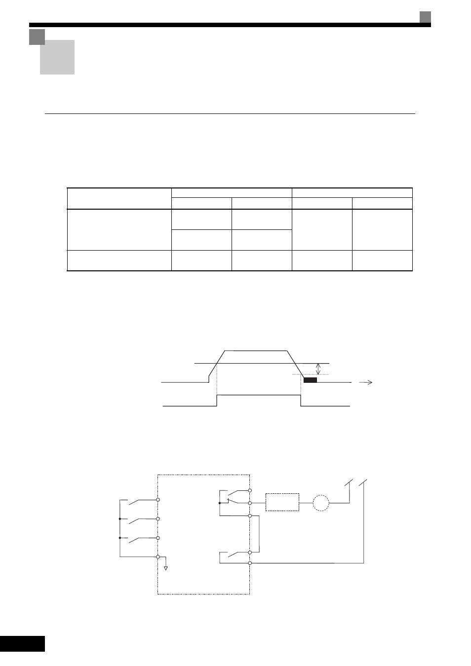
Fig 6.82
Sequence Circuit Configuration
The brake on/off sequence circuit configuration is shown below.
Note: Design the sequence so that the holding brake contact is open when the sequence operation conditions are satisfied and the contact between M1 and M2
is closed (on).
Make sure that the holding brake contact is closed when the emergency stop signal or MxC fault contact output signal is on.
Fig 6.83 Brake On/Off Sequence Circuit Configuration
Control Method
Brake On/Off Signal
Brake On/Off Level Adjustment
Signal Name
Parameter
*1
Signal Name
Parameter
V/f (A1-02 = 0)
Open Loop Vector
(A1-02 = 2, default)
Frequency
Detection 2
H2-01 = 05
*4
Frequency detec-
tion level and
detection width
L4-01 = 1.0 to 3.0
Hz
*2
, L4-02 = 0.1
to 0.5 Hz
*3
Frequency
Detection 5
H2-01 = 36
*4
Flux Vector (A1-02 = 3)
During Run 2
H2-01 = 37
Zero-speed level
(off timing only)
b2-01 = 0.1 to
0.5 Hz
L4-02
L4-01
off
on
Frequency detection 2
Output frequency
Time
BR
MxC
(Forward run)
UP
DOWN
HIGH/LOW
(Reverse run)
S2
(Multi-step speed reference 2)
MA
MB
S6
Fault contacts
S1
Holding brake
auxiliary relay coil
Sequence
circuit
Energizes the brake when ON
(250 Vac 1 A or less, 30 Vdc
1 A or less)
Frequency
detection 2 or
During run
M1
M2
SC
MC