Setting the awg control graphic – HEIDENHAIN SW 54843x-03 DIN Programming User Manual
Page 565
HEIDENHAIN MANUALplus 620, CNC PILOT 640
565
7.
2 A
u
to
matic w
o
rk
ing plan g
e
ner
a
tion (A
WG)
Machining sequence for rechucking
AWG control graphic
When you create a program with the AWG, the programmed blank
and finished part are displayed in the simulation window and in
addition, all machining steps are simulated successively. The
workpiece blank takes on a contour during machining.
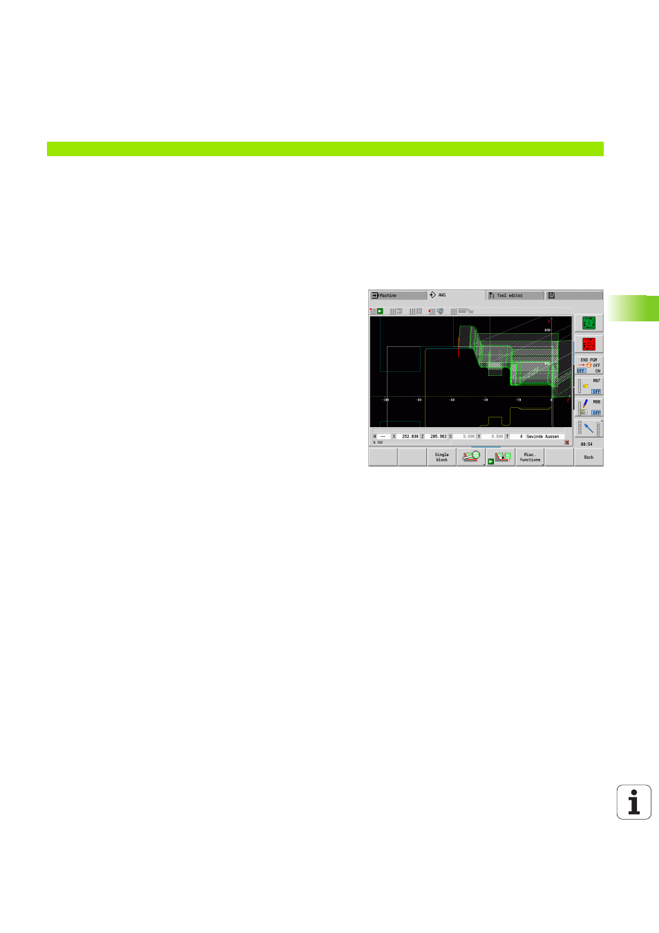
Setting the AWG control graphic
When you start the automatic program creation with the AWG soft
key, the control automatically opens the AWG control graphic. The
simulation displays dialogs in which you get machining and tool
information. After you have simulated the machining process, you can
close the graphics window with the "Back" soft key. The "Save as"
dialog box opens once you exit the TURN PLUS menu with the "Back"
soft key. The name of the opened program is displayed in the "File
name" dialog field. If you do not enter another file name, the opened
program will be overwritten. Alternatively, you can save the machining
operation in another program.
The AWG control graphic is indicated in the soft-key symbol by a
contour outlined in red.
You can set the display of the tool paths and the simulation mode
as usual (see "Graphic simulation" in the User's Manual).
Main machining
Submachining
Location
Execution
Rechucking
Full-surface machining
–
The workpiece is rechucked.