2 automatic working plan generation (awg), Generating a working plan – HEIDENHAIN SW 54843x-03 DIN Programming User Manual
Page 553
HEIDENHAIN MANUALplus 620, CNC PILOT 640
553
7.
2 A
u
to
matic w
o
rk
ing plan g
e
ner
a
tion (A
WG)
7.2
Automatic working plan
generation (AWG)
The AWG generates the work blocks of the working plan in the
sequence defined in "Machining sequence." You define the machining
details in the Machining Parameters input form. TURN PLUS
automatically finds all the elements of a work block. Use the
machining sequence editor to specify the machining sequence.
A work block has the following content:
Tool call
Cutting values (technology data)
Approach (may be omitted)
Machining cycle
Tool retraction (may be omitted)
Moving to tool change point (may be omitted)
You can change or supplement the generated work blocks
subsequently.
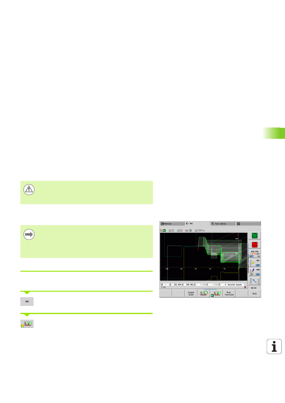
TURN PLUS simulates the machining in the AWG control graphic. You
can set the sequence and representation of the control graphic via soft
key (see "Graphic simulation" in the User's Manual).
Generating a working plan
Generating a working plan with TURN PLUS
Select "TURN PLUS." TURN PLUS opens the most recently selected
machining sequence.
Select "AWG." TURN PLUS shows the contours of the
blank and the finished part in the graphics window.
Press the "AWG control graphic" soft key: The AWG
control graphic and program generation are started.
TURN PLUS outputs warnings during the contour analysis
if certain areas cannot be machined at all or not
completely. Check the respective sections after program
creation and adapt them to your needs.
After generating the working plan, please note: If no
chucking equipment has been defined in the program as
yet, TURN PLUS defines the chucking equipment for a
specific type of clamping/clamping length and adjusts the
cutting limitation accordingly. Adapt the values in the
finished NC program.