Line segment in a contour g1-geo, 3 basic cont our elements – HEIDENHAIN SW 54843x-03 DIN Programming User Manual
Page 202
202
DIN Programming
4.3 Basic cont
our elements
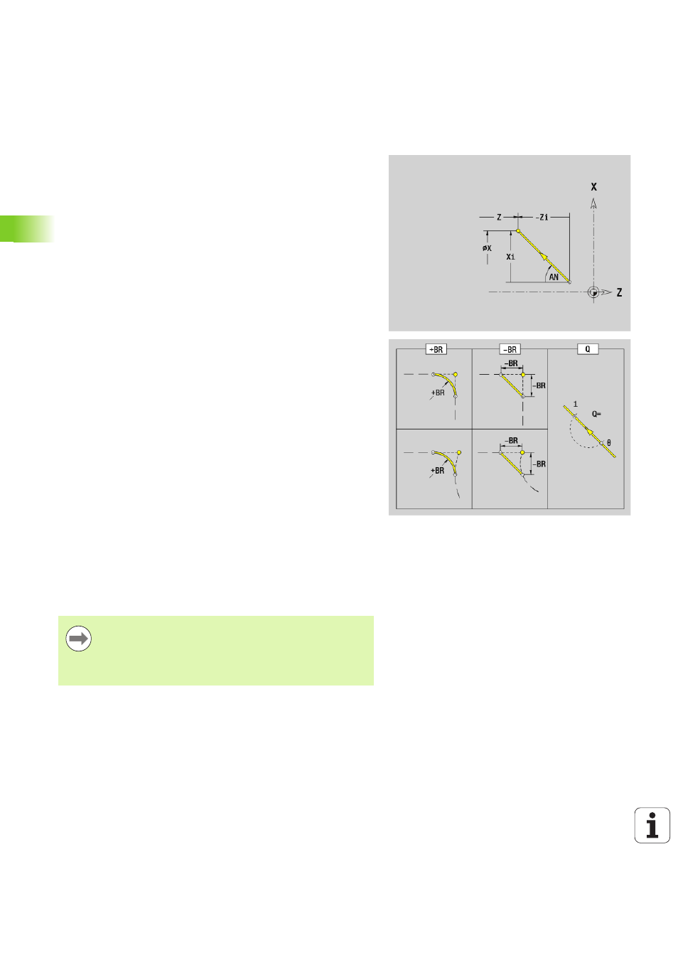
Line segment in a contour G1-Geo
G1 defines a line segment in a turning contour.
Parameters
X
End point of contour element (diameter value)
Z
End point of contour element
AN
Angle to rotary axis (for angle direction see graphic support
window)
Q
Point of intersection. End point if the line segment intersects a
circular arc (default: 0):
0: Near point of intersection
1: Far point of intersection
BR
Chamfer/rounding. Defines the transition to the next contour
element. When entering a chamfer/rounding, program the
theoretical end point.
No input: Tangential transition
BR=0: No tangential transition
BR>0: Radius of rounding
BR<0: Width of chamfer
PZ
End point of contour element (polar radius; reference:
workpiece zero point)
W
End point of contour element (polar angle; reference: workpiece
zero point)
AR
Angle to rotary axis (AR corresponds to AN)
R
Line length (polar radius; reference: last contour point)
BE, BF, BD, BP and BH (see „Machining attributes for form
elements” on page 201)
FP
Do not machine element (only necessary for TURN PLUS):
0: Do not machine basic element (straight line)
1: Do not machine overlay element (e.g. chamfer or rounding)
2: Do not machine basic/overlay element
IC
Measuring cut oversize (measuring cut diameter)
KC
Length of measuring cut
HC
Measuring cut counter: Number of workpieces after which a
measurement is performed
Programming
X, Z: Absolute, incremental, modal or "?"
ANi: Angle to the subsequent element
ARi: Angle to the previous element