Nc blocks of the din program, 1 pr ogr amming in din/iso mode – HEIDENHAIN SW 54843x-03 DIN Programming User Manual
Page 192
192
DIN Programming
4.1 Pr
ogr
amming in DIN/ISO mode
Contours for C-axis machining:
Contours for C-axis machining are programmed within the
FINISHED PART section.
Identify the contours as FACE or LATERAL. You can use section
codes more than once or program multiple contours within one
section code.
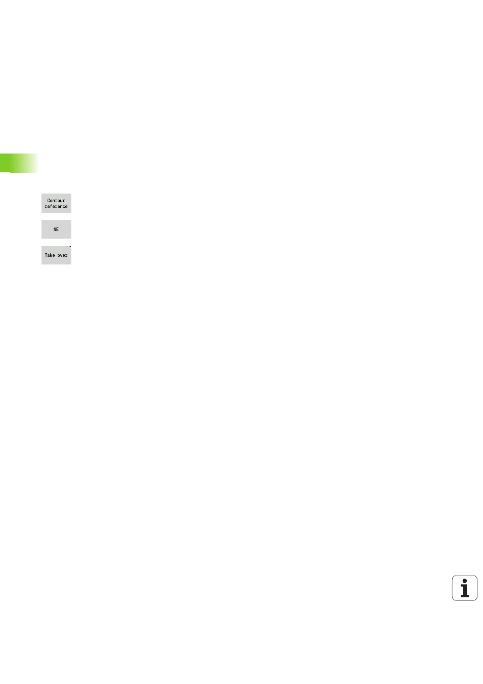
Block references: When editing G commands related to the contour
(MACHINING section), load the block references from the displayed
contour.
Place the cursor in the input box (NS).
Switch to the contour display.
Place the cursor on the desired contour element.
Switch to NE.
Place the cursor on the desired contour element.
Press the LOAD soft key to return to the dialog.
NC blocks of the DIN program
An NC block contains NC commands such as positioning, switching
or organizational commands. Traversing and switching commands
begin with G or M followed by a number (G1, G2, G81, M3, M30, ...)
and the address parameters. Organizational commands consist of key
words (WHILE, RETURN, etc.), or of a combination of letters/
numbers.
You can also program NC blocks containing only variable calculations.
You can program several NC commands in one NC block, provided
they have different address letters and do not have opposing
functions.
Examples
Permissible combination: N10 G1 X100 Z2 M8
Non-permissible combination:
N10 G1 X100 Z2 G2 X100 Z2 R30 (same address letters are used
more than once) or
N10 M3 M4 (opposing functionality)
NC address parameters
The address parameters consist of 1 or 2 letter(s) followed by
A value
A mathematical expression
A question mark—simplified geometry programming (VGP)
A letter "i" to designate incremental address parameters (examples:
Xi..., Ci..., XKi..., YKi..., etc.)
A # variable
A constant (_constname)