26 milling cy cles – HEIDENHAIN SW 54843x-03 DIN Programming User Manual
Page 362

362
DIN Programming
4.26 Milling cy
cles
Parameters—Milling
NE
Block number—end of contour section
Figures, free closed contour: No input
Free open contour: Last contour element
Contour consists of one element:
No input: Machining in contour direction
NS=NE programmed: Machining against the contour
direction
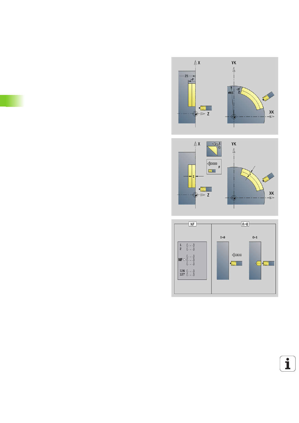
H
Cutting direction (default: 0)
0: Up-cut milling
1: Climb milling
I
(Maximum) infeed (default: milling in one infeed)
F
Infeed rate (depth infeed)—(default: active feed rate)
E
Reduced feed rate for circular elements (default: current feed
rate)
R
Radius of approaching/departing arc (default: 0)
R=0: Contour element is approached directly; infeed to
starting point above the milling plane, then vertical plunge.
R>0: Tool moves on approaching/departing arc that
connects tangentially to the contour element.
R<0 for inside corners: Tool moves on approaching/
departing arc that connects tangentially to the contour
element.
R<0 for outside corners: Contour element is approached/
departed tangentially on a linear path
P
Milling depth (default: depth from the contour description)
XS
Milling top edge—lateral surface (replaces the reference plane
from the contour definition)
ZS
Milling top edge—face (replaces the reference plane from the
contour definition)
RB
Retraction plane (default: back to starting position)
Front or rear face: Retraction position in Z direction
Lateral surface: Retraction position in X direction (diameter)
D
Starting element number when partial figures are machined.
V
End element number when partial figures are machined.
The direction of contour definition for figures is
counterclockwise. The first contour element for figures:
Circular slot: The larger arc
Full circle: The upper semicircle
Rectangles, polygons and linear slots: The orientation angle
points to the first contour element.
A
Sequence for "Milling, deburring": A=0 (default=0)
NF
Position mark—reference from which the cycle reads the hole
positions [1 to 127].
