Monitoring zone g995, 29 other g codes – HEIDENHAIN SW 54843x-03 DIN Programming User Manual
Page 388
388
DIN Programming
4.29 Other G codes
Monitoring zone G995
G995 defines the monitoring zone and the axes to be monitored. The
monitoring zone corresponds to the program section that is to be
monitored by the control.
To begin the monitoring zone, program G995 with the following
parameters. To end the monitoring zone, program G995 without
parameters.
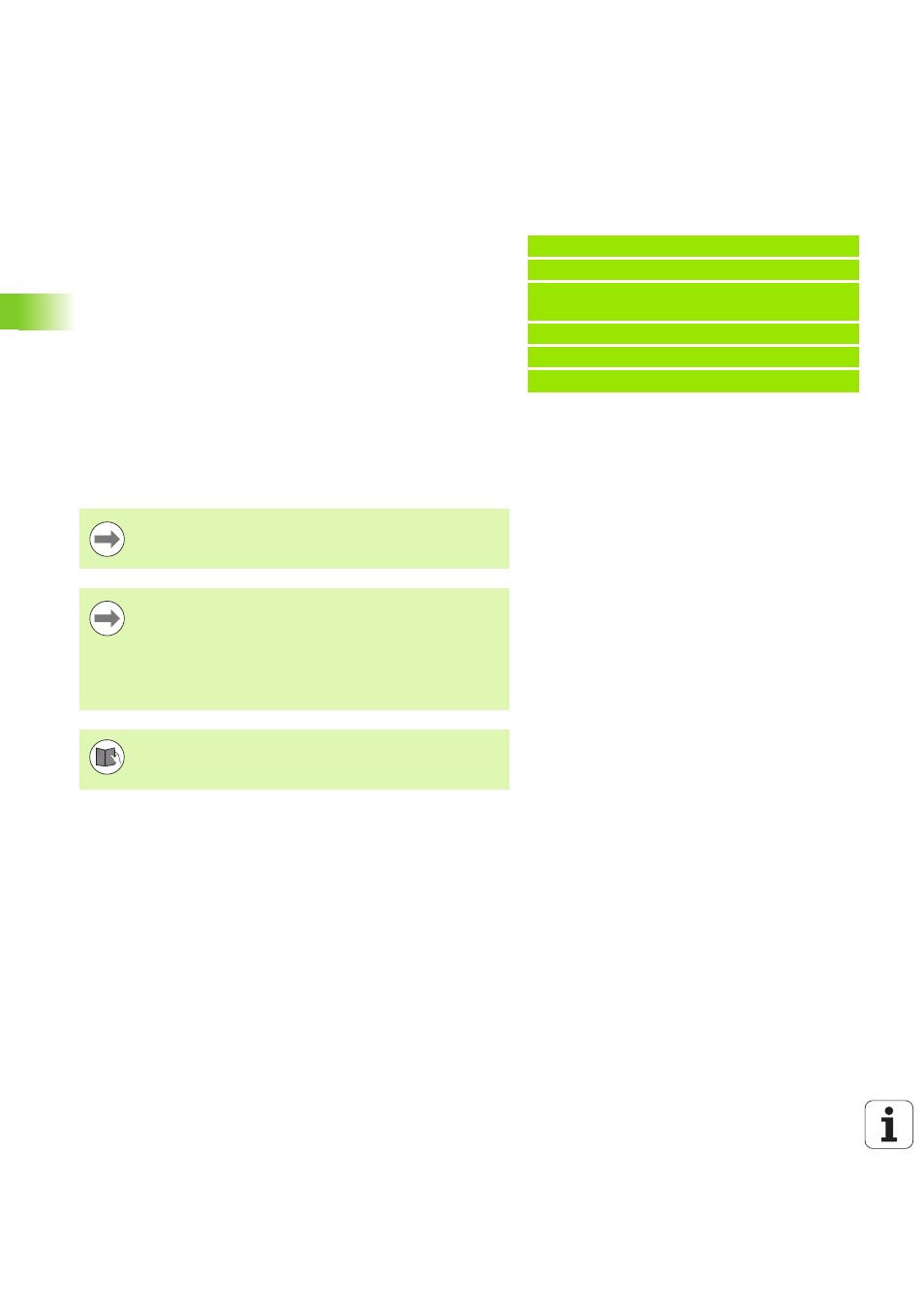
Beispiel: G995
. . .
N1 T4
N2 G995 H1 ID"X0" [Beginning of monitoring
zone; monitoring of X axis and main spindle]
. . . [Machining]
G995 [End of monitoring zone]
. . .
Parameters
H
No. of the zone (range: 1 to 99)
ID
Code for axes
X: X axis
Y: Y axis
Z: Z axis
0: Spindle 1 (main spindle, C axis)
1: Spindle 2
2: Spindle 3
The monitoring zones must be unambiguously defined in
the program. Use the H parameter to assign a unique
number to each monitoring zone.
If you would like to monitor more than one drive within a
monitoring zone, enter the respective combination of
individual parameters in the ID parameter. Please keep in
mind, however, that the control can monitor a maximum
of four drives per monitoring zone. To simultaneously
monitor the Z axis and the main spindle, enter Z0 in the ID
parameter.
In addition to defining the monitoring zone with G995, you
need to activate the load monitoring function (see „Load
monitoring G996” on page 389).