26 milling cy cles – HEIDENHAIN SW 54843x-03 DIN Programming User Manual
Page 353

HEIDENHAIN MANUALplus 620, CNC PILOT 640
353
4.26 Milling cy
cles
Contour and figure milling cycle, lateral surface
G794
G794 mills figures or (open or closed) "free" contours.
G794 is followed by:
The figure to be milled with:
Contour definition of the figure (G311 to G317)—See "Lateral
surface contours" on page 239.
Conclusion of contour definition (G80)
The free contour with:
Starting point (G110)
Contour definition (G111, G112, G113)
Conclusion of contour definition (G80)
Beispiel: G794
%314_G315.nc
[G314 / G315]
N1 T7 G197 S1200 G195 F0.2 M104
N2 M14
N3 G110 C0
N4 G0 X110 Z5
N5 G794 XS100 XE97 P2 U0.5 R0 K0.5 F0.15
N6 G314 Z-35 C0 R20
N7 G80
N8 M15
END
Preferentially use ICP and the G840, G845 and G846
cycles to program the contour description in the geometry
section.
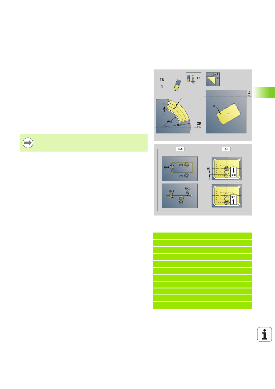
Parameters
XS
Milling top edge (diameter value)
XE
Milling floor (diameter value)
P
Maximum approach (default: total depth in one infeed)
U
Overlap factor—contour milling or pocket milling (default: 0)
U=0: Contour milling
U>0: Pocket milling—minimum overlap of milling paths =
U*milling diameter
R
Approach radius (radius of approaching/departing arc)—
(default: 0)
R=0: Contour element is approached directly; infeed to
starting point above the milling plane—then vertical plunge
R>0: Tool moves on approaching/departing arc that
connects tangentially to the contour element
R<0 for inside corners: Tool moves on approaching/
departing arc that connects tangentially to the contour
element
R<0 for outside corners: Length of linear approaching/
departing element; contour element is approached/departed
tangentially
I
Oversize X
K
Contour-parallel oversize
F
Infeed rate
E
Reduced feed rate for circular elements (default: current feed
rate)
H
Cutting direction (default: 0): The cutting direction can be
changed with H and the direction of tool rotation.
0: Up-cut milling
1: Climb milling
