Zero point offsets—shift g53/g54/g55, Additive zero point shift g56, 13 zer o point shif ts – HEIDENHAIN SW 54843x-03 DIN Programming User Manual
Page 261: Zero point offsets
HEIDENHAIN MANUALplus 620, CNC PILOT 640
261
4.13 Zer
o
point shif
ts
Zero point offsets
—
Shift G53/G54/G55
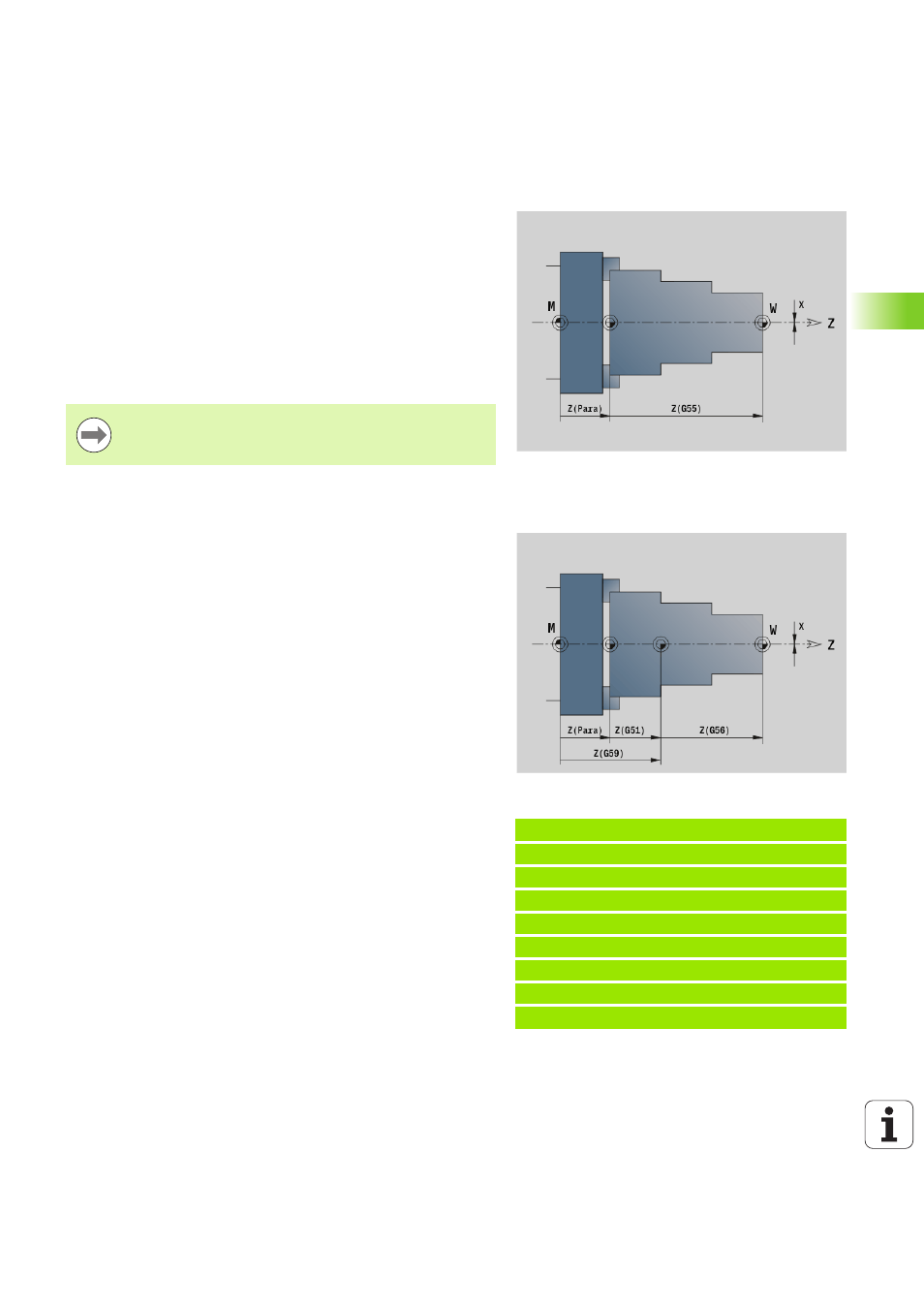
G53, G54 and G55 shift the workpiece zero point by the offset values
defined in setup mode.
The shift is referenced to the workpiece zero point defined in setup
mode, even if you shift the zero point several times with G53, G54 and
G55.
The shift remains in effect until the end of the program or until it is
canceled by other zero point shifts.
Before using zero point shifts with G53, G54 and G55, you need to
define the offset values in setup mode (see "Defining offsets" in the
User's Manual).
Additive zero point shift G56
G56 shifts the workpiece zero point by the defined value in the
selected axis. The shift is referenced to the currently active workpiece
zero point.
If you shift the workpiece zero point more than once with G56, the
shift is always added to the currently active zero point.
A shift in X is entered as a radius.
Beispiel: G56
. . .
N1 T3 G95 F0.25 G96 S200 M3
N2 G0 X62 Z5
N3 G810 NS7 NE12 P5 I0.5 K0.2
N4 G56 Z-28 [zero point shift]
N5 G0 X62 Z5
N6 G810 NS7 NE12 P5 I0.5 K0.2
N7 G56 Z-28 [zero point shift]
. . .
Parameters
X
Shift (radius value)—(default: 0)
Y
Shift (machine-dependent)
Z
Shift
U
Shift (machine-dependent)
V
Shift (machine-dependent)
W
Shift (machine-dependent)