Approach tool change point g14, Definition of tool-change point g140, 9 t o ol positioning – HEIDENHAIN SW 54843x-03 DIN Programming User Manual
Page 249
HEIDENHAIN MANUALplus 620, CNC PILOT 640
249
4.9 T
o
ol positioning
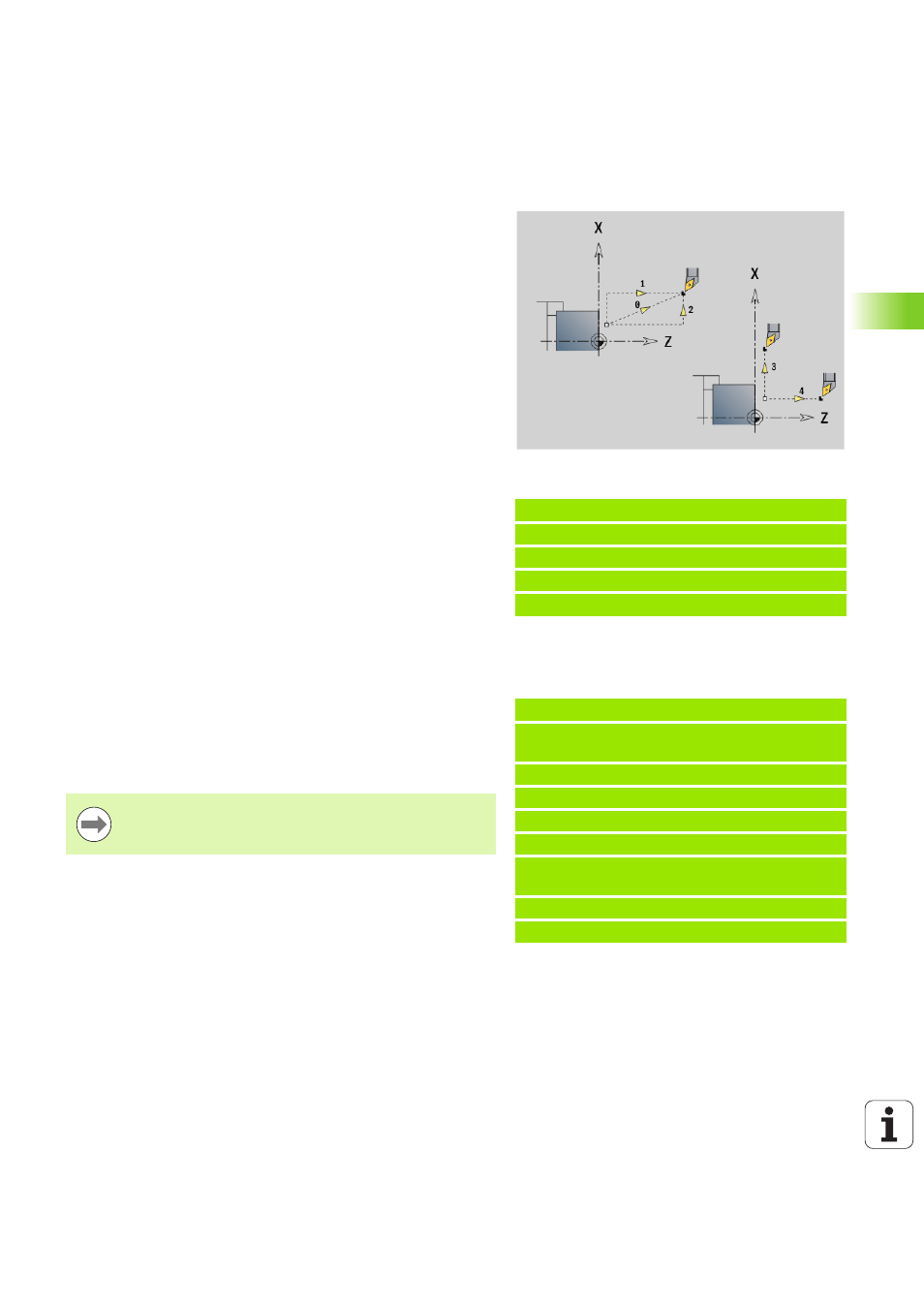
Approach tool change point G14
G14 moves the slide at rapid traverse to the tool change position. In
setup mode, define permanent coordinates for the tool change
position.
Definition of tool-change point G140
G140 defines the position of the tool change point defined in D. This
position can be approached with G14.
Beispiel: G14
. . .
N1 G14 Q0 [Move to tool change point]
N2 T3 G95 F0.25 G96 S200 M3
N3 G0 X0 Z2
. . .
Parameters
Q
Sequence. Determines the course of traverse movements
(default: 0)
0: Diagonal path of traverse
1: First X, then Z direction
2: First Z, then X direction
3: Only X direction, Z remains unchanged
4: Only Z direction, X remains unchanged
D
Number of the tool change position to be approached (0-2)
(default =0, tool change position from parameters)
Beispiel: G140
. . .
N1 G14 Q0 [Tool change position from
parameter]
N2 T3 G95 F0.25 G96 S200 M3
N3 G0 X40 Z10
N5 G140 D1 X100 Z100 [Set tool change pos. 1]
N6 G14 Q0 D1 [Move to tool change pos. 1]
N7 G140 D2 X150 [Set tool change pos. 2, use
Z from parameters]
N8 G14 Q0 D2 [Move to tool change pos. 2]
. . .
Parameters
D
Number of the tool change point (1-2)
X
Diameter—Position of the tool change point
Z
Length—Position of the tool change point
If X or Z parameters are missing, the values from the tool
change point parameter are entered.