Circular arc of turning contour g12/g13-geo, 3 basic cont our elements – HEIDENHAIN SW 54843x-03 DIN Programming User Manual
Page 205

HEIDENHAIN MANUALplus 620, CNC PILOT 640
205
4.3 Basic cont
our elements
Circular arc of turning contour G12/G13-Geo
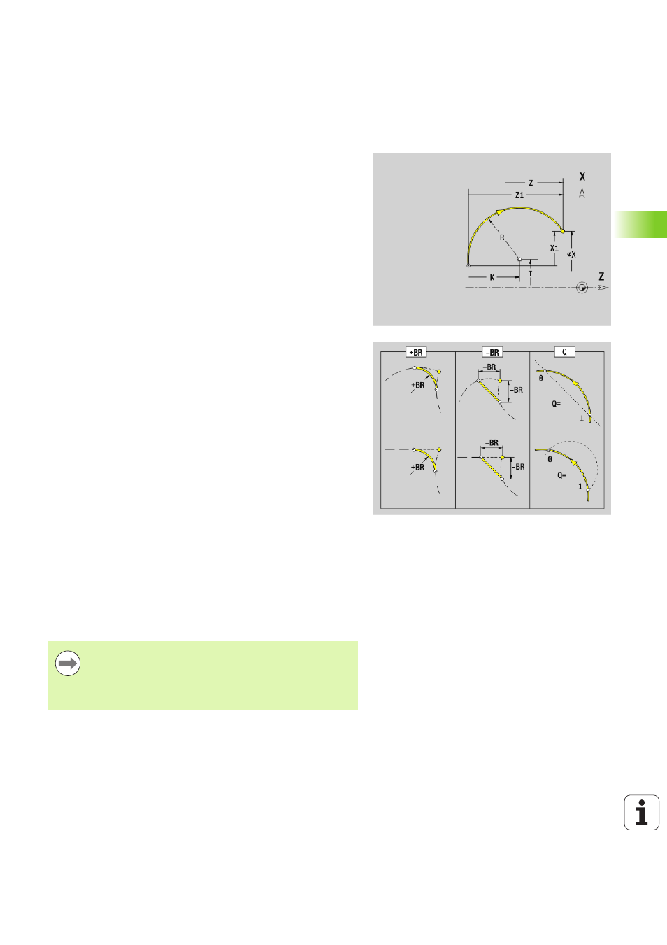
G12/G13 defines a circular arc in a contour with absolute center
dimensioning. Direction of rotation (see help graphic):
G12: In clockwise direction
G13: In counterclockwise direction
Parameters
X
End point of contour element (diameter value)
Z
End point of contour element
I
Center (radius dimension)
K
Center
R
Radius
Q
Point of intersection. End point if the circular arc intersects a
line segment or another circular arc (default: 0):
0: Near point of intersection
1: Far point of intersection
BR
Chamfer/rounding. Defines the transition to the next contour
element. When entering a chamfer/rounding, program the
theoretical end point.
No input: Tangential transition
BR=0: No tangential transition
BR>0: Radius of rounding
BR<0: Width of chamfer
PZ
End point of contour element (polar radius; reference:
workpiece zero point)
W
End point of contour element (polar angle; reference:
workpiece zero point)
PM
Center point (polar radius; reference: workpiece zero point)
WM Center point (polar angle; reference: workpiece zero point)
AR
Starting angle (tangential angle to rotary axis)
AN
End angle (tangential angle to rotary axis)
BE, BF, BD, BP and BH (see „Machining attributes for form
elements” on page 201)
FP
Do not machine element (only necessary for TURN PLUS):
0: Do not machine basic element (straight line)
1: Do not machine overlay element (e.g. chamfer or rounding)
2: Do not machine basic/overlay element
Programming
X, Z: Absolute, incremental, modal or "?"
ARi: Angle to the previous element
ANi: Angle to the subsequent element
