Laser mapping – Hypertherm V9 Series Phoenix Rev.11 User Manual
Page 78
78
Phoenix 9.76.0 Installation and Setup Manual 806410
2 – Machine Setup
Laser Mapping
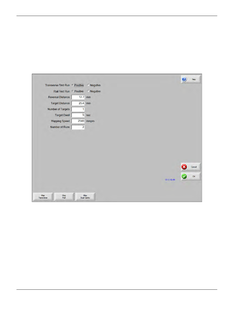
The Laser Mapping screen provides an interface for the laser interferometer. The CNC uses the parameters in the Laser
Mapping screen to generate a CNC part program that allows the laser interferometer to map the position of each drive
axis (rail, transverse, and dual gantry) at specified points (or targets).
After the parameters are set and the laser interferometer is connected to the axis, press the mapping soft key for the
appropriate axis. The CNC will automatically load and run the part program.
Rail/Transverse First Run: The direction of the first run on the Rail or Transverse axis. The selection should be based
on the direction of motion from home position.
Reversal Distance: The distance of travel in the opposite direction at the beginning and end of a run.
Use: Reverse motion removes mechanical backlash before mapping the axis.
Target Distance: Sets the distance between targets.
Use: This value should be 20 inches or more.
Number of Targets: The number of pauses on each run where the laser interferometer measures the physical position of
the axis. The part program that the CNC creates for mapping includes a pause (dwell) at each of these
targets.
Use: Enter values between 2 and 1000.