Hypertherm V9 Series Phoenix Rev.11 User Manual
Page 66
66
Phoenix 9.76.0 Installation and Setup Manual 806410
2 – Machine Setup
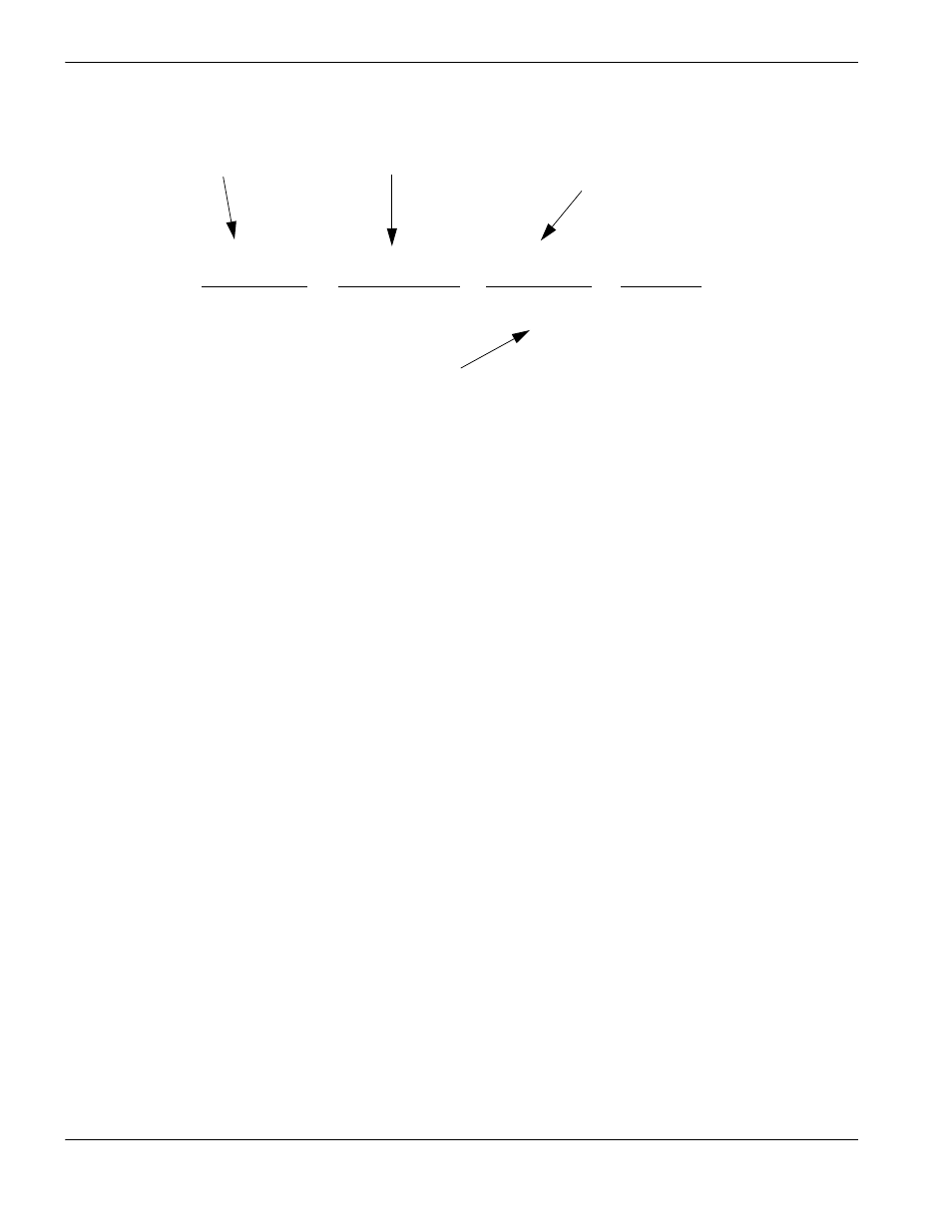
An example of the equation is shown below:
Drive Type: This parameter is used to tell the CNC what type of control loop to run. If you are running an external velocity
loop drive (indicated by having an integrated tachometer in the motor), select Velocity. If you are running in
torque mode (no tachometer), select Current.
DAC Polarity: This parameter allows changing the analog output polarity to establish proper control loop feedback
without any wiring changes.
Encoder Polarity: This parameter allows changing the encoder input polarity to establish proper counting for positive
machine motion without any wiring changes.
Encoder Decode Mode: Currently the CNC only supports 4X encoder decode mode. This has been done to increase
positional accuracy.
Use Home Limit Switch: Selecting “Yes” will enable the Home feature for the Dual Gantry Axis.
The Z Home Switch must first be defined and mapped to an input location in the screen
to enable this feature.
Switch Offset Distance: The Switch Offset Distance is used to specify any physical position offset between the Dual
Gantry and Rail Home Switch positions. This allows the CNC to position the two axes accurately for
operation and remove any skew of the gantry.
Backlash Compensation: The Backlash Compensation parameter is used to offset or compensate for any backlash in
the mechanics of the drive system.
Laser Compensation: Uses position readings gathered with a laser interferometer to correct the actual position of the
axes (Transverse, Dual Transverse, Rail, and Dual Gantry only).
4000 counts
x
10 rev of motor
x
1 rev
=
X counts
1 revolution
1 rev of pinion
2
Π inches
inches
1000 line encoder multiplied
by 4 (quadrature) per 1 motor
revolution
10:1 gear ratio
Distance traveled in one
revolution of the pinion
Circumference of pinion (2 inch
diameter multiplied by
pi)
Encoder counts per unit
(inches or mm)