Cds multihead groups, Differences between cds modes, Example of use – Guntermann & Drunck DVICenter DP16 Config Panel User Manual
Page 179: Differences between cds modes example of use, Monitor 2, Monitor 1
CDS multihead groups
G&D DVICenter · 177
CDS multihead groups
CDS multihead groups
let you create a
CDS workplace. You can switch any video chan-
nel to the monitors of this workplace.
The video channel can be either the (only) video channel of a computer with one graph-
ics output only or a given video channel of a computer with multiple graphics outputs.
The configuration settings of a CDS multihead group provide the matrix switch with
the resolutions and order of connected video channels belonging to one display range
of a computer. These information allow flexible switching via CDS.
Differences between CDS modes
CDS multihead groups expand the functional range of CrossDisplay-Switching (CDS):
Up to firmware version 1.1, the matrix switch supported only
CDS with channel
groups
in multihead environments.
In this mode, the matrix switch can display an additional video channel (added
via channel group) of a computer with multiple graphics outputs only on monitors
of user modules that also have a compatible channel group
Showing the first video channel of another target on an additional monitor of a chan-
nel group is not possible.
CDS with multihead groups
lets you display on every monitor either the (only) video
channel of a computer with one graphics output or a given video channel of a com-
puter with multiple graphics outputs.
Example of use
The following example shows the difference between the two CDS modes:
IMPORTANT:
If two different users operate two different targets of a CDS multi-
head group at the same time, the mouse jumps between the affected video chan-
nels of both users.
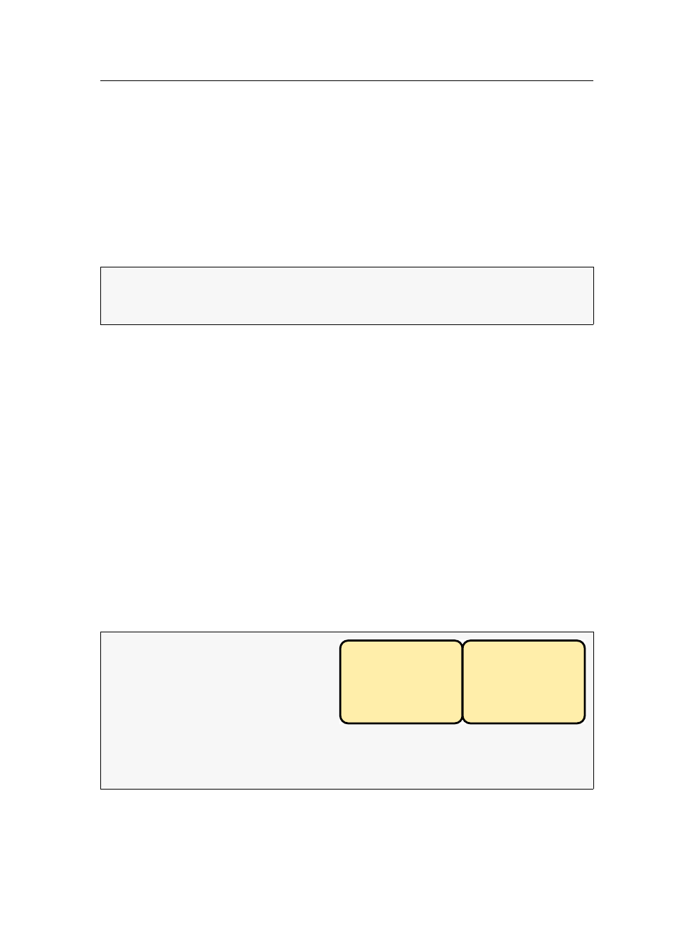
EXAMPLE:
A display range of
3840×1200 pixels is defined in the
graphics settings of a computer. The
computer uses two video channels
with 1920×1200 pixels each to trans-
mit the display range to two moni-
tors:
You can use a target module
DVI-U-CPU-MC2
, for example, to connect the computer
to the matrix switch.
Monitor 1
1920×1200
Monitor 2
1920×1200