2 diagnostic word – Pilz PNOZ mm0p 24VDC User Manual
Page 59
Fieldbus modules
Operating Manual PNOZmulti communication interfaces
1001154-EN-13
59
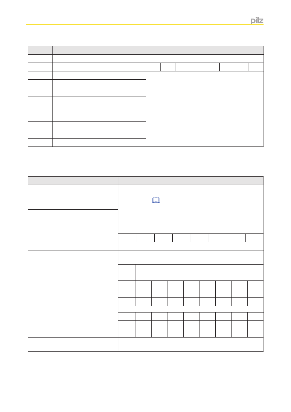
Byte
Content
Example/explanation
117
O16 ... O23 4th expansion module, left
Byte 114:
118
O24 ... O31 4th expansion module, left
O31 O30 O29 O28 O27 O26 O25 O24
119
O0 ... O7 5th expansion module, left
If an output has a high signal, the corresponding Bit
will contain "1"; if the output is open (low signal), the
Bit will contain "0".
120
O8 ... O15 5th expansion module, left
121
O16 ... O23 5th expansion module, left
122
O24 ... O31 5th expansion module, left
123
O0 ... O7 6th expansion module, left
124
O8 ... O15 6th expansion module, left
125
O16 ... O23 6th expansion module, left
126
O24 ... O31 6th expansion module, left
127
Reserved
Diagnostic word
The following bytes contain the diagnostic words and the output bits for the Element IDs.
Byte
Content
Example/explanation
128
Low Byte diagnostic word.
Element ID=1
The diagnostic word is displayed in the PNOZmulti Configurator
and on the PVIS expanded diagnostics (see chapter entitled
and the online help for the PNOZmulti
Configurator)
Element ID = 1,
e.g. diagnostic word of E-STOP:
Low Byte:
...
227
Low Byte diagnostic word.
Element ID=100
0
0
0
0
0
0
1
0
Message: Pushbutton operated
228 ...
240
Output Bits of Element ID =
1 ... 100
Each element is assigned an ID in the PNOZmulti Configurator. If
the element's output = 0 (no enable), the corresponding bit is set.
Sub
Index
Element ID
101
8
7
6
5
4
3
2
1
102
16
15
14
13
12
11
10
9
103
24
23
22
21
20
19
18
17
111
88
87
86
85
84
83
82
81
112
96
95
94
93
92
91
90
89
113
-
-
-
-
100
99
98
97
241 ...
255
Reserved
4.5.3.2
- PNOZ mm0.1p PNOZ mm0.2p PNOZ mml1p PNOZ mml2p PNOZ mmc1p ETH PNOZ mmc2p seriell PNOZ mmc3p DP PNOZ mmc6p CAN PNOZ mmc4p DN PNOZ m1p base unit PNOZ m1p base unit coated version PNOZ m0p base unit not expandable PNOZ m2p base module press function PNOZ m3p base unit burner function PNOZ m1p ETH PNOZ m3p ETH PNOZ m0p ETH PNOZ m2p ETH PNOZ m1p ETH coated version PNOZ mi1p 8 input PNOZ mi1p 8 input coated version PNOZ mo1p 4 so PNOZ mo1p 4so coated version PNOZ mo3p 2so PNOZ mo2p 2n/o PNOZ mo2p 2n/o coated version PNOZ mo5p 4 n/o burner PNOZ mo4p 4n/o PNOZ mo4p 4n/o coated version PNOZ ml1p safe link 24VDC PNOZ ml2p safe link PDP PNOZ ms1p standstill / speed monitor PNOZ ms2p PNOZ ma1p 2 Analog Input PNOZ ms3p standstill / speed monitor PNOZms2p HTL PNOZ ma1p coated version PNOZ ml1p coated version PNOZ ms2p TTL coated version PNOZ ms3p HTL PNOZ ms2p TTL PNOZ ms3p TTL PNOZ mi2p 8 standard input PNOZ mc1p PNOZ mc1p coated version PNOZ mc0p Powersupply PNOZ mc5p Interbus PNOZ mc7p CC-Link coated version PNOZ mc7p CC-Link PNOZ mc6p CANopen coated version PNOZmc5.1p Interbus LWL / Fiberoptic PNOZ mc4p DeviceNet coated version PNOZ mc8p Ethernet IP / Modbus TCP PNOZ mc9p Profinet IO PNOZ mc3p Profibus 2 PNOZ mc8p coated version PNOZ mc6p CANopen 2 PNOZ mc4p DeviceNet 2 PNOZ mc2.1p EtherCAT 2 PNOZ mc10p SERCOS III PNOZ mc7p CC-Link 2 PNOZ mc6.1p CANopen 3