Pilz PNOZ mm0p 24VDC User Manual
Page 30
Fieldbus modules
Operating Manual PNOZmulti communication interfaces
1001154-EN-13
30
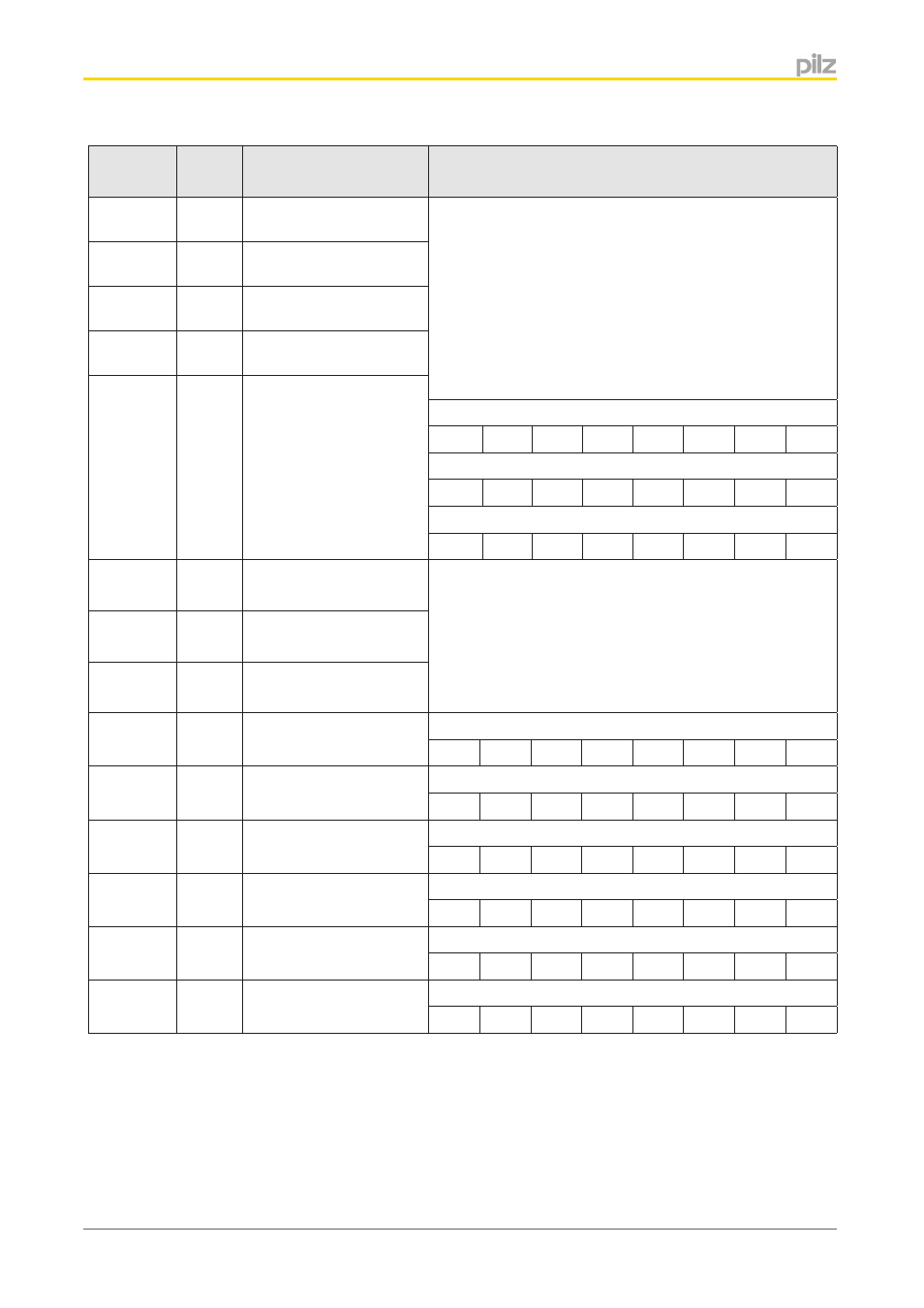
Index
(hex)
Input
Byte
Content
Example/Comment
0x2003:A
393
I0 ... I7 5th expansion
module, right
If an input has a high signal, the corresponding bit will be
"1"; if an input has a low signal, the bit will be "0".
INFORMATION:
On the base units PNOZmulti Mini, the status of the con-
figurable inputs/outputs is only displayed if they are con-
figured as inputs in the PNOZmulti Configurator.
Assignment of Bytes on the base units PNOZmulti Mini:
0x2003:B
394
I0 ... I7 6th expansion
module, right
0x2003:C
395
I0 ... I7 7th expansion
module, right
0x2003:D
396
I0 ... I7 8th expansion
module right
0x2003:E
...
0x2003:10
397
...
399
Reserved
Sub-Index 1: PNOZ mmxp
I7
I6
I5
I4
IM3
IM2
IM1
IM0
Sub-Index 2: PNOZ mmxp
I15
I14
I13
I12
I11
I10
I9
I8
Sub-Index 3: PNOZ mmxp
0
0
0
0
IM19 IM18 IM17 IM16
0x2003:11 400
LED I0 ... I7 base unit
For example: The safety system consists of one base unit
PNOZ m1p and one expansion module PNOZ mi1p
0x2003:12 401
LED I8 ... I15 base unit
0x2003:13 402
LED I16 ... I19 base unit
0x2003:14 403
0
Sub-Index 11: PNOZ m1p
I7
I6
I5
I4
I3
I2
I1
I0
0x2003:15 404
0
Sub-Index 12: PNOZ m1p
I15
I14
I13
I12
I11
I10
I9
I8
0x2003:16 405
LED I0 ... I7 1st expan-
sion module, right
Sub-Index 13: PNOZ m1p
0
0
0
0
I19
I18
I17
I16
0x2003:17 406
LED I0 ... I7 2nd expan-
sion module, right
Sub-Index 14:
0
0
0
0
0
0
0
0
0x2003:18 407
LED I0 ... I7 3rd expan-
sion module, right
Sub-Index 15:
0
0
0
0
0
0
0
0
0x2003:19 408
LED I0 ... I7 4th expan-
sion module, right
Sub-Index 16: PNOZ mi1p
I7
I6
I5
I4
I3
I2
I1
I0
- PNOZ mm0.1p PNOZ mm0.2p PNOZ mml1p PNOZ mml2p PNOZ mmc1p ETH PNOZ mmc2p seriell PNOZ mmc3p DP PNOZ mmc6p CAN PNOZ mmc4p DN PNOZ m1p base unit PNOZ m1p base unit coated version PNOZ m0p base unit not expandable PNOZ m2p base module press function PNOZ m3p base unit burner function PNOZ m1p ETH PNOZ m3p ETH PNOZ m0p ETH PNOZ m2p ETH PNOZ m1p ETH coated version PNOZ mi1p 8 input PNOZ mi1p 8 input coated version PNOZ mo1p 4 so PNOZ mo1p 4so coated version PNOZ mo3p 2so PNOZ mo2p 2n/o PNOZ mo2p 2n/o coated version PNOZ mo5p 4 n/o burner PNOZ mo4p 4n/o PNOZ mo4p 4n/o coated version PNOZ ml1p safe link 24VDC PNOZ ml2p safe link PDP PNOZ ms1p standstill / speed monitor PNOZ ms2p PNOZ ma1p 2 Analog Input PNOZ ms3p standstill / speed monitor PNOZms2p HTL PNOZ ma1p coated version PNOZ ml1p coated version PNOZ ms2p TTL coated version PNOZ ms3p HTL PNOZ ms2p TTL PNOZ ms3p TTL PNOZ mi2p 8 standard input PNOZ mc1p PNOZ mc1p coated version PNOZ mc0p Powersupply PNOZ mc5p Interbus PNOZ mc7p CC-Link coated version PNOZ mc7p CC-Link PNOZ mc6p CANopen coated version PNOZmc5.1p Interbus LWL / Fiberoptic PNOZ mc4p DeviceNet coated version PNOZ mc8p Ethernet IP / Modbus TCP PNOZ mc9p Profinet IO PNOZ mc3p Profibus 2 PNOZ mc8p coated version PNOZ mc6p CANopen 2 PNOZ mc4p DeviceNet 2 PNOZ mc2.1p EtherCAT 2 PNOZ mc10p SERCOS III PNOZ mc7p CC-Link 2 PNOZ mc6.1p CANopen 3