6 reaction time, Reaction time – Pilz PNOZ mm0p 24VDC User Manual
Page 121
Safe Ethernet connection
Operating Manual PNOZmulti communication interfaces
1001154-EN-13
121
The Modbus address at which the PNOZmulti makes the send/receive data available as
Server is not configurable in the PNOZmulti.
The PNOZmulti's send data (18 Register) can be found from start address 20000 (signifies
HoldingRegister 4x20000)
The PNOZmulti's receive data (18 Register) can be found from start address 21000 (signi-
fies HoldingRegister 4x21000)
These addresses must be configured accordingly in the PSS 4000.
Reaction time
The safety function's safe reaction time is composed of the reaction times of the control
systems and the monitoring time for a telegram's runtime.
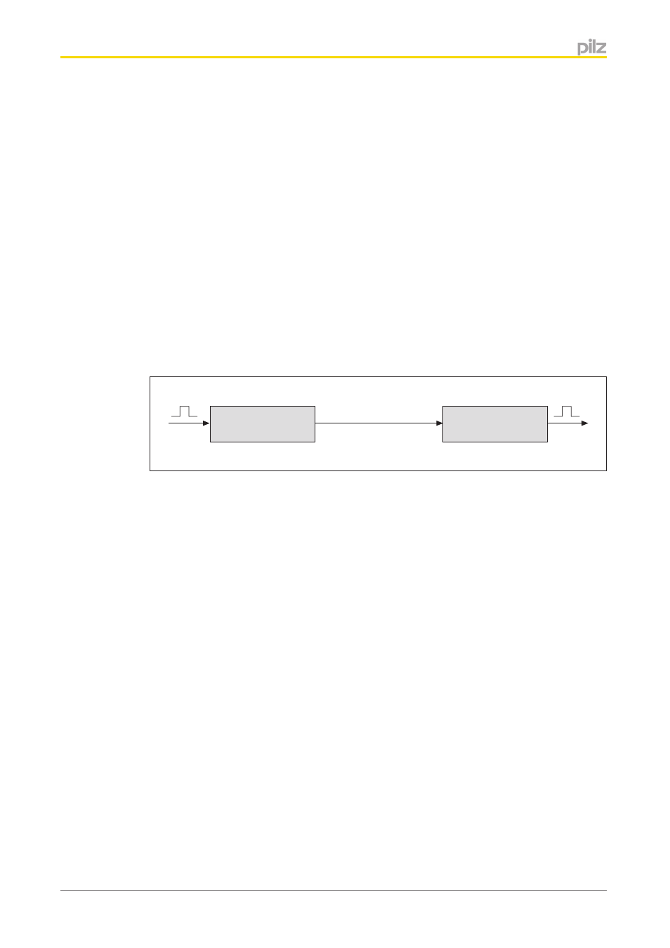
Composition of the entire data path
The entire data path is composed of the data subpaths of a control system 1, the safe Eth-
ernet connection and the data subpaths of a control system 2.
Control system 1
Control system 2
[1]
[3]
[2]
Safe Ethernet connection
Data path 1: Control system 1 (transmitter)
Data path 1 describes the time between the signal changing at the input of control system 1
and the signal being present in the
Safe Ethernet connection output area of control sys-
tem 1.
If control system 1 (transmitting system) is an automation system PSS 4000, you can calcu-
late the reaction time of this data path as described in the online help for PAS4000.
If control system 1 (transmitting system) is a control system PNOZmulti, you can calculate
the reaction time as follows:
}
Max. input delay (see Technical details in the operating instructions for the respective
input) + Max. cycle time of the device (see base unit's operating instructions)
Data path 2: Safe Ethernet connection (transmission)
Data path 2 describes the time between the signal being present in the
Safe Ethernet con-
nection output area of control system 1 and the signal being present in the Safe Ethernet
connection input area of control system 2.
The reaction time of data path 2 corresponds to the configured timeout time t
SecTimeout
of the
receiver system.
7.6
- PNOZ mm0.1p PNOZ mm0.2p PNOZ mml1p PNOZ mml2p PNOZ mmc1p ETH PNOZ mmc2p seriell PNOZ mmc3p DP PNOZ mmc6p CAN PNOZ mmc4p DN PNOZ m1p base unit PNOZ m1p base unit coated version PNOZ m0p base unit not expandable PNOZ m2p base module press function PNOZ m3p base unit burner function PNOZ m1p ETH PNOZ m3p ETH PNOZ m0p ETH PNOZ m2p ETH PNOZ m1p ETH coated version PNOZ mi1p 8 input PNOZ mi1p 8 input coated version PNOZ mo1p 4 so PNOZ mo1p 4so coated version PNOZ mo3p 2so PNOZ mo2p 2n/o PNOZ mo2p 2n/o coated version PNOZ mo5p 4 n/o burner PNOZ mo4p 4n/o PNOZ mo4p 4n/o coated version PNOZ ml1p safe link 24VDC PNOZ ml2p safe link PDP PNOZ ms1p standstill / speed monitor PNOZ ms2p PNOZ ma1p 2 Analog Input PNOZ ms3p standstill / speed monitor PNOZms2p HTL PNOZ ma1p coated version PNOZ ml1p coated version PNOZ ms2p TTL coated version PNOZ ms3p HTL PNOZ ms2p TTL PNOZ ms3p TTL PNOZ mi2p 8 standard input PNOZ mc1p PNOZ mc1p coated version PNOZ mc0p Powersupply PNOZ mc5p Interbus PNOZ mc7p CC-Link coated version PNOZ mc7p CC-Link PNOZ mc6p CANopen coated version PNOZmc5.1p Interbus LWL / Fiberoptic PNOZ mc4p DeviceNet coated version PNOZ mc8p Ethernet IP / Modbus TCP PNOZ mc9p Profinet IO PNOZ mc3p Profibus 2 PNOZ mc8p coated version PNOZ mc6p CANopen 2 PNOZ mc4p DeviceNet 2 PNOZ mc2.1p EtherCAT 2 PNOZ mc10p SERCOS III PNOZ mc7p CC-Link 2 PNOZ mc6.1p CANopen 3