6 instruction timing, Cpu timing, Scillator – Maxim Integrated High-Speed Microcontroller User Manual
Page 64: Xtal1, Xtal2, Haracteristics, Rystal, Election
High-Speed Microcontroller User’s Guide
Rev: 062210
64 of 176
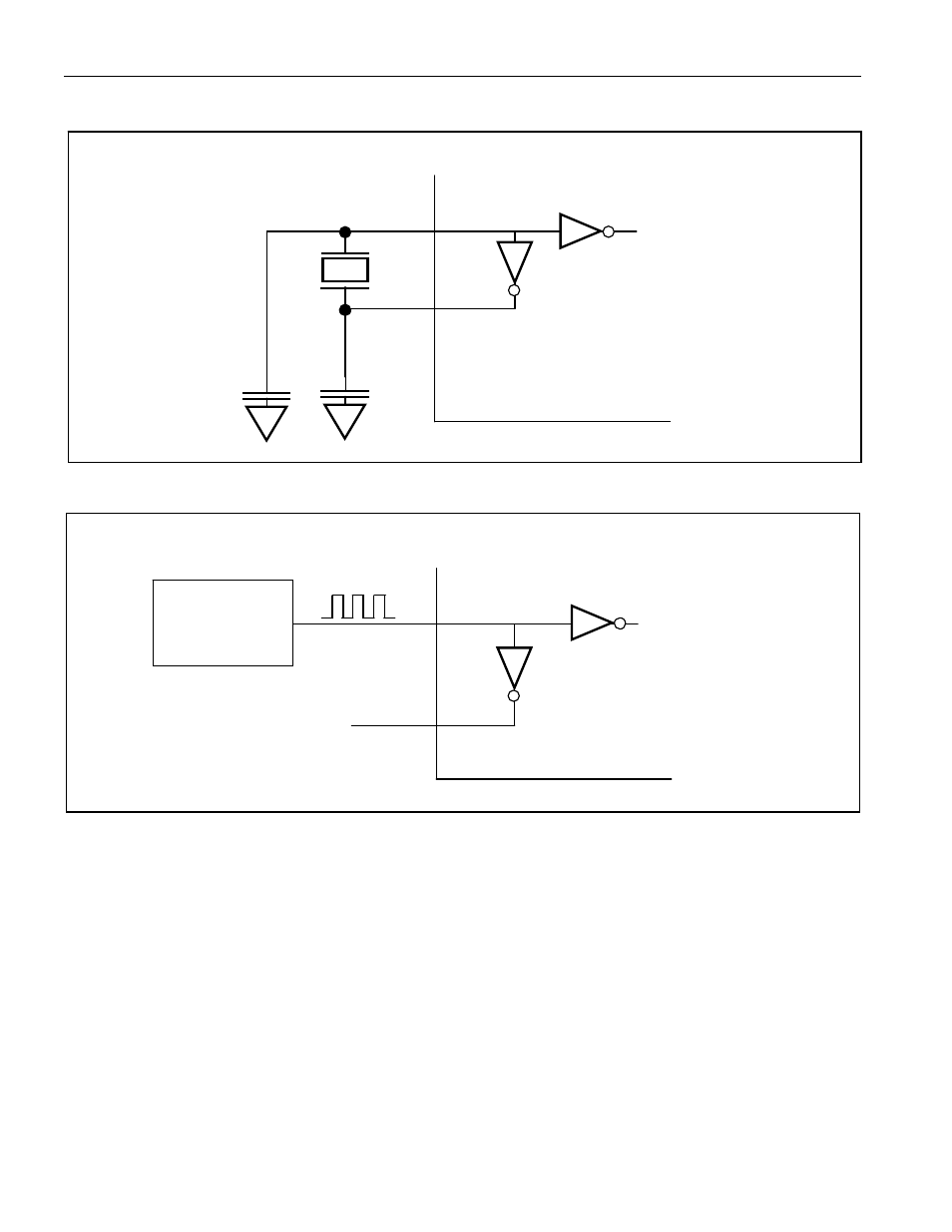
Figure 5-1. Crystal Connection
Figure 5-2. Clock Source Input
5.6 Instruction Timing
The clock source, whether crystal or oscillator, supplies the internal functions with a precise time base.
The clock is used to create the basic unit of timing called a machine cycle. One machine cycle consists of
four clocks when operating in divide-by-4 mode. The use of Power Management modes will cause the
device to utilize 64 or 1024 external clock cycles per machine cycle. Within a machine cycle there are
four states called C1, C2, C3, and C4. Various operations take place during each C state. Within this
section and throughout others, an event timing will be identified by its C state. For example, ALE rises at
the beginning of the C1 time. Since the clock source is the source of nearly all timing, the electrical
specifications are given in terms of clocks. The time of a clock period is referred to as t
CLCL
.
Most times in the electrical specifications are specified as some number of clocks from the edge of a
signal. The signal edges were also derived from the clock source and the C states.
TO INTERNAL
CIRCUITS
XTAL1
XTAL2
HIGH-SPEED
MICROCONTROLLER
33pF
33pF
TO INTERNAL
CIRCUITS
XTAL1
XTAL2
HIGH-SPEED MICRO
CLOCK
OSCILLATOR