1 timer mode control register (tmod) summary, Programmable timers, Imers – Maxim Integrated High-Speed Microcontroller User Manual
Page 119
High-Speed Microcontroller User’s Guide
Rev: 062210
119 of 176
location of their flags. The registers are described below. Following this is a detailed explanation of the
four operating modes.
Each timer consists of a 16-bit register in two bytes. These are called
,
,
, and
. As
shown, each timer is broken into low and high bytes. Software
can read or write any of these locations at
any time.
11.1.1
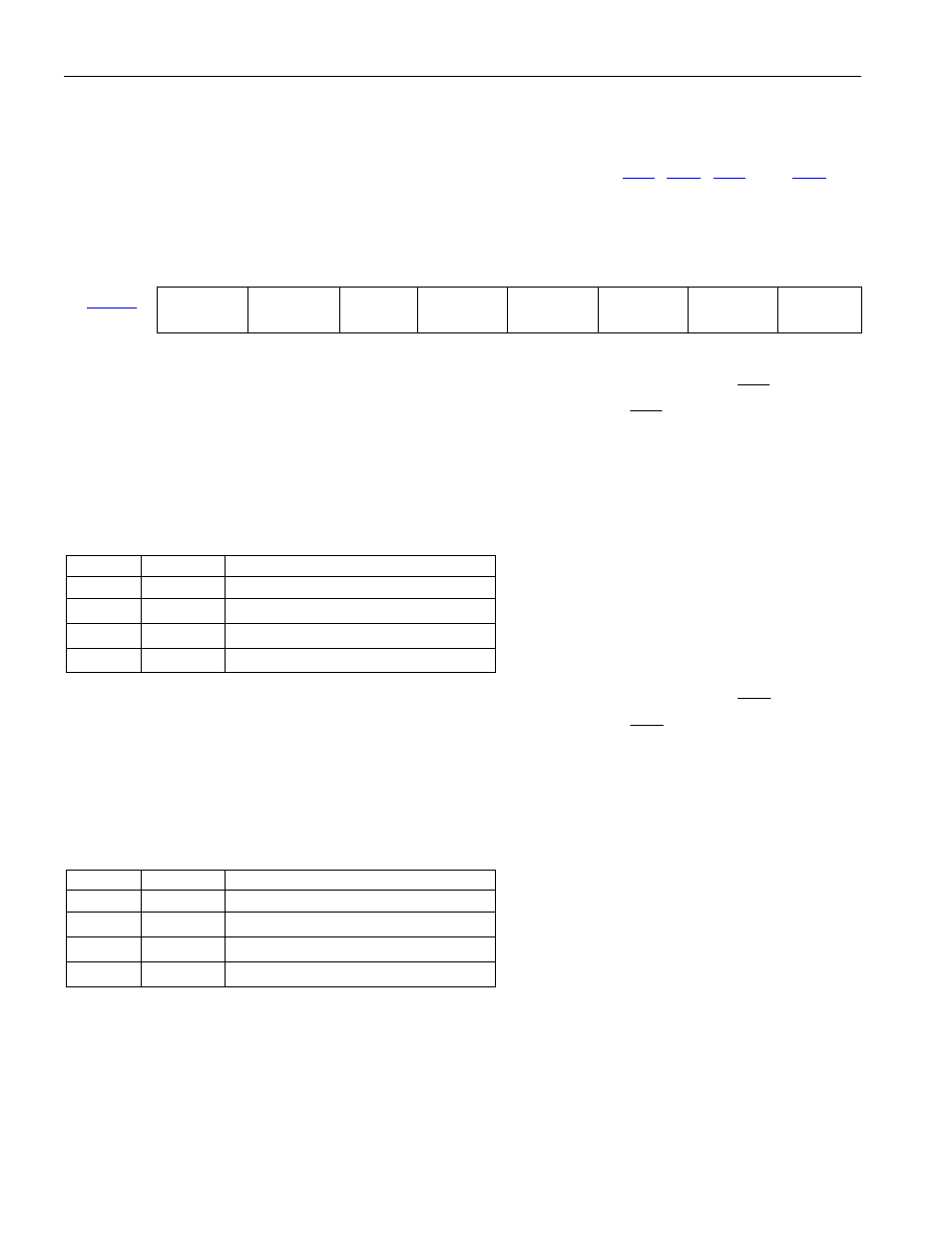
Timer Mode Control Register (TMOD) Summary
7 6 5 4 3 2 1 0
89h
GATE
C/
T M1 M0 GATE C/T
M1 M0
Bit 7: Timer 1 Gate Control (GATE). When GATE = 1, Timer 1 will clock only when
INT1
and TR1 =
1. When GATE = 0, Timer 1 will clock only when TR1 = 1 irrespective of
INT1
.
Bit 6: Counter/Timer Select (C/
T). When C/T is set to a 0, Timer 1 is incremented by internal clocks.
When C/
T is set to a 1, Timer 1 counts based on the T1 (P3.5) pin.
Bits 5 and 4: Timer 1 Mode Select Bit 1 and 0 (M[1:0])
M1 M0
MODE
0
0
Mode 0: 8 bits with 5-bit prescale
0
1
Mode 1: 16 bits
1
0
Mode 2: 8 bits with auto-reload
1
1
Mode 3: Timer 1 stopped
Bit 3: Timer 0 Gate Control (GATE). When GATE = 1, Timer 0 will clock only when
INT0
and TR0 =
1. When GATE = 0, Timer 0 will clock only when TR0 = 1 irrespective of
INT0
.
Bit 2: Counter/Timer Select (C/
T). When C/T is set to a 0, Timer 0 is incremented by internal clocks.
When C/
T is set to a 1, Timer 0 counts based on the T0 (P3.4) pin.
Bits 1 and 0: Timer 0 Mode Select Bit 1 and 0 (M[1:0])
M1 M0
MODE
0
0
Mode 0: 8 bits with 5-bit prescale
0
1
Mode 1: 16 bits
1
0
Mode 2: 8 bits with auto-reload
1
1
Mode 3: Timer 0 is two 8-bit timers