37 timer 2 capture lsb (rcap2l), 38 timer 2 capture msb (rcap2h), 39 timer 2 lsb (tl2) – Maxim Integrated High-Speed Microcontroller User Manual
Page 48: 40 timer 2 msb (th2), Timer 2 mode (t2mod), Rcap2l, Rcap2h, Tl2.7
High-Speed Microcontroller User’s Guide
Rev: 062210
48 of 176
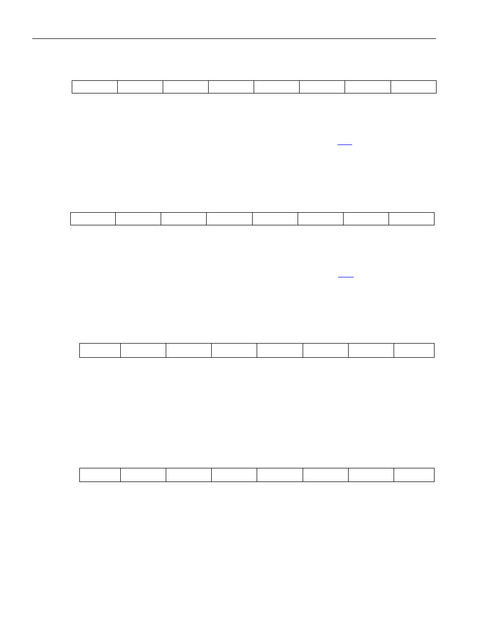
4.2.37
Timer 2 Capture LSB (RCAP2L)
7 6 5 4 3 2 1 0
SFR CAh RCAP2L.7 RCAP2L.6 RCAP2L.5 RCAP2L.4 RCAP2L.3 RCAP2L.2 RCAP2L.1 RCAP2L.0
RW-0 RW-0 RW-0 RW-0 RW-0 RW-0 RW-0 RW-0
R = Unrestricted Read, W = Unrestricted Write, -n = Value after Reset
RCAP2L.7–
RCAP2L.0
Bits 7–0
Timer 2 Capture LSB. This register is used to capture the
value when timer 2 is
configured in capture mode. RCAP2L is also used as the LSB of a 16-bit reload value
when timer 2 is configured in auto-reload mode.
4.2.38
Timer 2 Capture MSB (RCAP2H)
7 6 5 4 3 2 1 0
SFR CBh RCAP2H.7 RCAP2H.6 RCAP2H.5 RCAP2H.4 RCAP2H.3 RCAP2H.2 RCAP2H.1 RCAP2H.0
RW-0 RW-0 RW-0 RW-0 RW-0 RW-0 RW-0 RW-0
R = Unrestricted Read, W = Unrestricted Write, -n = Value after Reset
RCAP2H.7–
RCAP2H.0
Bits 7–0
Timer 2 Capture MSB. This register is used to capture the
value when timer 2 is
configured in capture mode. RCAP2H is also used as the MSB of a 16-bit reload value
when timer 2 is configured in auto-reload mode.
4.2.39
Timer 2 LSB (TL2)
7 6 5 4 3 2 1 0
SFR CCh
TL2.7 TL2.6 TL2.5
TL2.4 TL2.3 TL2.2
TL2.1 TL2.0
RW-0 RW-0 RW-0 RW-0 RW-0 RW-0
RW-0 RW-0
R = Unrestricted Read, W = Unrestricted Write, -n = Value after Reset
TL2.7–TL2.0
Bits 7–0
Timer 2 LSB. This register contains the least significant byte of Timer 2.
4.2.40
Timer 2 MSB (TH2)
7 6 5 4 3 2 1 0
SFR CDh
TH2.7
TH2.6
TH2.5
TH2.4 TH2.3 TH2.2
TH2.1 TH2.0
RW-0 RW-0 RW-0 RW-0 RW-0 RW-0
RW-0 RW-0
R = Unrestricted Read, W = Unrestricted Write, -n = Value after Reset
TL2.7–TL2.0
Bits 7–0
Timer 2 MSB. This register contains the least significant byte of Timer 2.