4 mode 2, Figure 11-1. timer/counter 0 and 1, modes 0 and 1 – Maxim Integrated High-Speed Microcontroller User Manual
Page 122
High-Speed Microcontroller User’s Guide
Rev: 062210
122 of 176
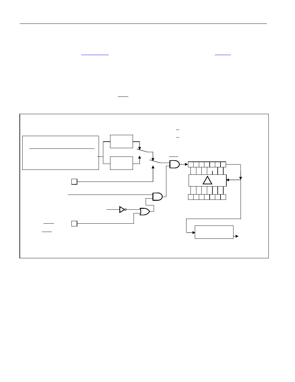
11.4 Mode 2
This mode configures the timer as an 8-bit timer/counter with automatic reload of the start value. This
configuration is shown in
, and is selected when bits M1 and M0 of the
register are set
to 1 and 0 respectively. When configured in Mode 2, the timer uses TLn to count and THn to store the
reload value. Software must initialize both TLn and THn with the same starting value for the first count to
be correct. Once the TLn reaches FFh, it will be automatically loaded with the value in THn. The THn
value remains unchanged unless modified by software. Mode 2 is commonly used to generate baud rates
since it runs without continued software intervention. As in modes 0 and 1, mode 2 allows counting of
either oscillator cycles (crystal/12 or crystal/4) or pulses on pin Tn (C/T = 1) when counting is enabled by
TRn and the proper setting of GATE and
INTn
pins.
Figure 11-2. Timer/Counter 0 and 1, Mode 2
OSC INPUT TO TIMER
CLK MODE
TIMER INPUT
DIVIDE-BY-4 OSC/1
PMM1
OSC/16
2PMM2
OSC/256
DIVIDE
BY 12
DIVIDE
BY 4
T0 = P3.4
(T1 = P3.5)
TR0 = TCON.4
(TR1 = TCON.6)
GATE = TMOD.3
(GATE = TMOD.7)
TF0 = TCON.5
(TF1 = TCON.7)
TIMER 1 FUNCTIONS
SHOWN IN PARENTHESES ()
INTERRUPT
TL0
(TL1)
0
7
0
7
TH0
(TH1)
0
1
0
1
T0M = CKCON.3
(T1M = CKCON.4)
RELOAD
C/
T = TMOD.2
(C/
T = TMOD.6)
INT0 = P3.2
(
INT1 = P3.3)
CLK