8 time base selection, Timer output clock generator, Ock output on port pin p1.0 (t2) as shown in – Maxim Integrated High-Speed Microcontroller User Manual
Page 131: Figure 11-7
High-Speed Microcontroller User’s Guide
Rev: 062210
131 of 176
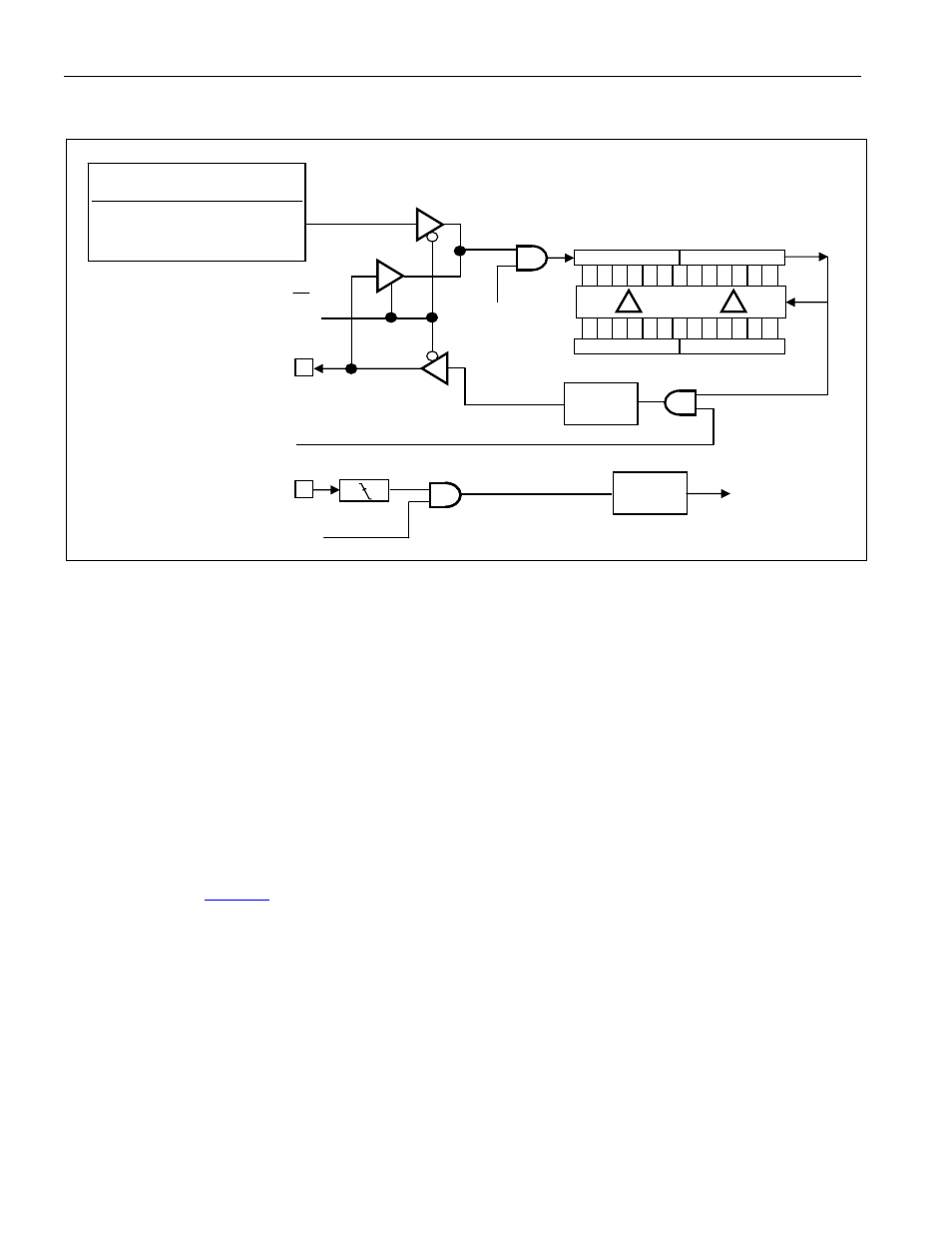
Figure 11-7. Timer/Counter 2, Clock-Out Mode
11.8 Time Base Selection
The high-speed microcontroller allows the user to select either 4 or 12 clocks as the time base for each
timer independently. When using the 16-bit Timer/Counters in timer mode, the timer/counter counts the
oscillator cycles divided by a predetermined number. In the standard 8051, the 8051 timers count the
oscillator divided by 12, which is the standard 8051-machine cycle timing. The high-speed
microcontroller allows the option of setting the timers to operate from a divide-by-4 of the input clock to
allow higher precision timing and faster baud rates. This selection has no effect on CPU timing, only on
the timers. Following a reset, the timers default to 12 clocks as the time base to remain drop-in
compatible with the original 8051.
The 4- or 12-clock decision is independent for each timer and the default is 12 clocks per timer tick. As
an example, a user might select both the baud-rate generator timer and one other timer to run at 12 clocks
per timer tick with the third timer at 4 clocks per tick. This allows one timer to measure higher speed
events or to gain better resolution. The control bits for the time-base selection are located in the Clock
Control register (
;8Eh). Timer 2 will function at 2 clocks per tick when set for baud-rate
generation or clock output as described above. When the time base is derived from an external source
(i.e., the T0, T1, or T2 pins), the timer operates at the frequency of the external source and is not affected
by the setting of the T0M, T1M, or T2M bits. The only limitation is that the external source frequency
can be no faster than 1/8 of the main oscillator frequency.
The use of power management modes will affect the input clock to the timer as shown in the illustrations.
In general, they will divide the input clock by either 16 or 256 for PMM1 and PMM2, respectively. Timer
2, when operating in baud-rate generator or clock-out mode normally uses the input clock frequency
divided by 2, but when PMM1 and PMM2 are used, it will operate from a time base of the input clock
divided by 32 and 512, respectively.
OSC INPUT TO TIMER
CLK MODE
TIMER INPUT
DIVIDE-BY-4 OSC/2
PMM1
OSC/32
PMM2
OSC/512
EXF2 =
T2CON.6
DIVIDE
BY 2
T2EX = P1.1
EXEN2 = T2CON.3
RCAP2L
RCAP2H
0
15
TL2
TH2
0
7
8
15
T2 = P1.0
7 8
C/T2 =
T2CON.1
= 0
TR2 =
T2CON.2
T2OE =
T2MOD.1
TIMER 2
INTERRUPT
F_OUT=
OSC INPUT
TO TIMER
[4 x (65536 -
RCAP2H,
RCAP2L)]