4 in-system disable mode, External reset, Eset – Maxim Integrated High-Speed Microcontroller User Manual
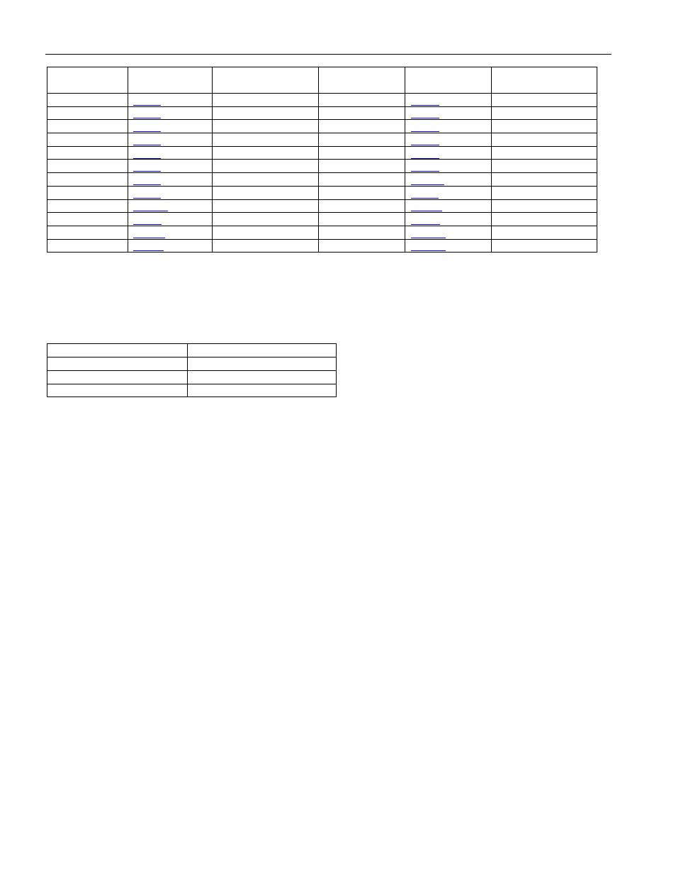
Page 104: Tate, Attery, Table 8-a. no-battery reset default
High-Speed Microcontroller User’s Guide
Rev: 062210
104 of 176
BIT NAME
LOCATION
NO-BATTERY
RESET STATE
BIT NAME
LOCATION
NO-BATTERY
RESET STATE
E4K
.7 0
SSCE
.7 Indeterminate
X12/6
.6 1
SCE
.6 Indeterminate
TRM2
.5 1
MCE
.5
Indeterminate
TRM2
.4 0
HCE
.4 Indeterminate
TRM1
.3 0
RTCIF
.1 Indeterminate
TRM1
.2 1
RTCE
.0 Indeterminate
TRM0
.1 0
RTCSS.7–0
.7–0 Indeterminate
TRM0
.0 1
.7–0 Indeterminate
RTASS.7–0
.7–0 Indeterminate
RTCM.7–0
.7–0 Indeterminate
RTAS.7–0
.7–0 Indeterminate RTCH.7–0
.7–0 Indeterminate
RTAM.7–0
.7–0 Indeterminate RTCD0.7–0
.7–0 Indeterminate
RTAH.7–0
.7–0 Indeterminate RTCD1.7–0
.7–0 Indeterminate
8.4 In-System Disable Mode
The high-speed microcontroller family supports in-circuit debugging of designs. The in-system disable
(ISD) feature allows the device to be three-stated for in-circuit emulation or board testing. During ISD
mode, the device pins will take on the following states:
DEVICE PIN
STATE DURING ISD
Port 0, 1, 2, 3 RST,
EA
True three-state
ALE,
PSEN
Weak Pullup (~10kΩ)
XTAL1, XTAL2
Oscillator remains active
The following procedure is used to enter ISD mode:
1) Assert reset by pulling RST high.
2) Pull ALE low and pull PSEN high.
3) Verify that P2.7, P2.6, P2.5 are not being driven low.
4) Release RST.
5) Hold ALE low and PSEN high for at least two machine cycles.
6) Device is now in ISD mode. Release ALE and PSEN if desired.
Note that pins P2.7, P2.6, P2.5 should not be driven low when RST is released. This will place the device
into a reserved test mode. Because these pins have a weak pullup during reset, they can be left floating.
The test mode is only sampled on the falling edge of RST, and once RST is released their state will not
affect device operation. In a similar manner, the PSEN and RST pins can be released once ISD mode is
invoked, and their state will not affect device operation. The RST pin will also be in a three-state mode,
but asserting it in ISD mode will return the device to normal operation.