6 timer 2, 1 timer two control register (t2con) summary, Figure 11-3. timer/counter 0 mode 3 – Maxim Integrated High-Speed Microcontroller User Manual
Page 124
High-Speed Microcontroller User’s Guide
Rev: 062210
124 of 176
11.6 Timer 2
Like Timers 0 and 1, Timer 2 is a full-function timer/counter, however it has several additional
capabilities that make it more useful. Timer 2 has independent control registers in
,
and is based on count registers
and
. All these registers are described in detail below.
11.6.1
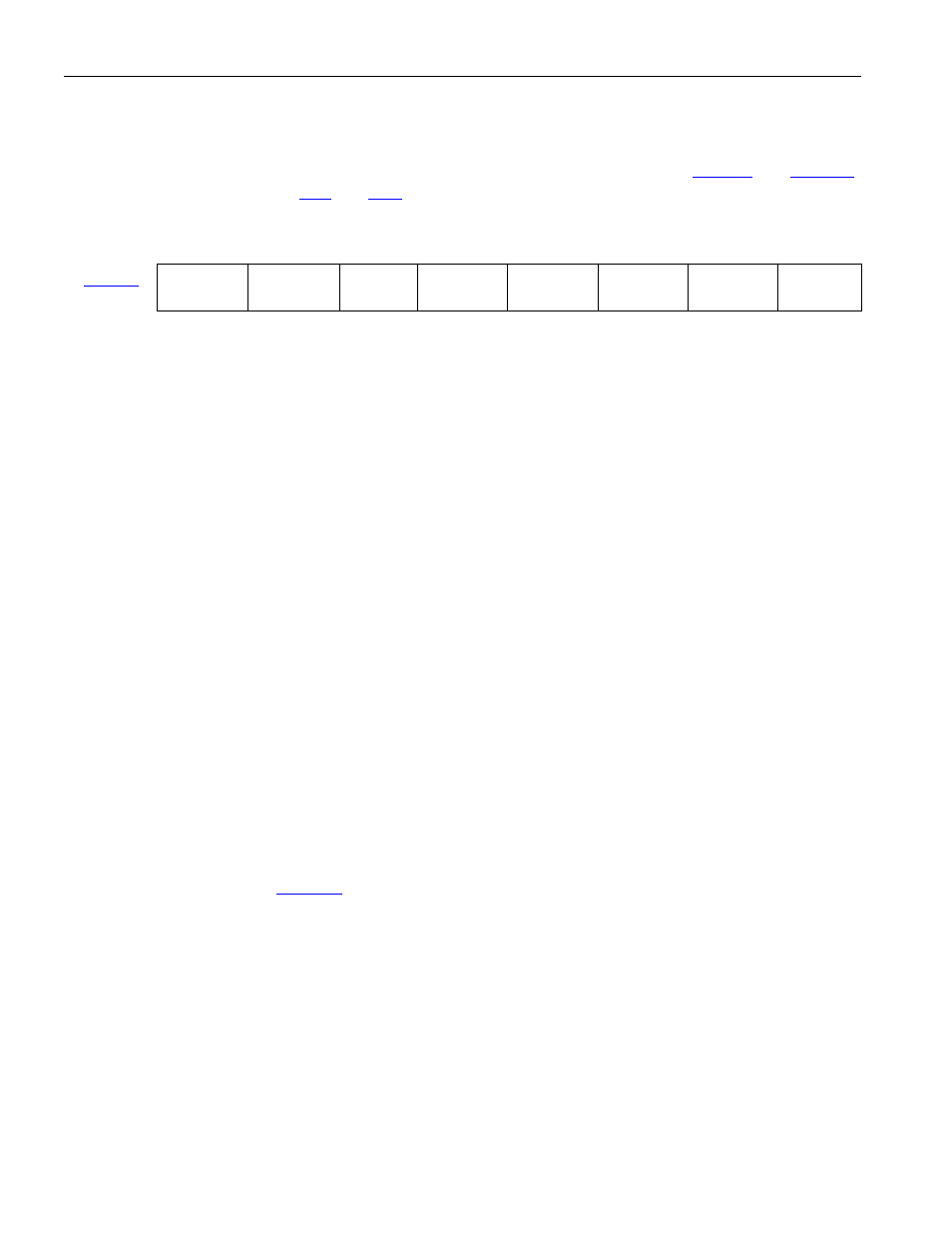
Timer Two Control Register (T2CON) Summary
7 6 5 4 3 2 1 0
C8h
TF2 EXF2
RCLK
TCLK EXEN2 TR2 C/T2 CP/RL2
Bit 7: Timer 2 Overflow Flag (TF2). Hardware will set TF2 when the Timer 2 overflows from FFFFh to
0000h, or from the count equal to the capture register in down count mode. It must be cleared to 0 by
software. TF2 will only be set to a 1 if RCLK and TCLK are both cleared to a 0.
Bit 6: Timer 2 External Flag (EXF2). Hardware will set EXF2 when a reload or capture is caused by a
falling transition on the T2EX pin (P1.1). EXEN2 must be set for this function. This flag must be cleared
to 0 by software. Writing a one to this bit will force a timer interrupt if enabled.
Bit 5: Receive Clock Flag (RCLK). This bit determines whether Timer 1 or 2 is used for Serial Port 0
timing of received data in Serial Modes 1 or 3. RCLK = 1 causes Timer 2 overflow to be used as the
receive clock. RCLK = 0 causes Timer 1 overflow to be used as the receive clock.
Bit 4: Transmit Clock Flag (TCLK). This bit determines whether Timer 1 or 2 is used for Serial Port 0
timing of Transmit data in Serial Modes 1 or 3. TCLK = 1 causes Timer 2 overflow to be used as the
transmit clock. TCLK = 0 causes Timer 1 overflow to be used as the transmit clock.
Bit 3: Timer 2 External Enable (EXEN2). Setting this bit to a 1 allows a capture or reload to occur as a
result of a falling transition on T2EX (P1.1), if Timer 2 is not generating baud rates for the serial port.
EXEN2 = 0 causes Timer 2 to ignore all external events at T2EX.
Bit 2: Timer 2 Run (TR2). Setting this bit to a 1 starts Timer 2. Setting it to a 0 stops Timer 2.
Bit 1: Counter/Timer Select (C/
T2). Setting this bit to a 0 selects a timer function for Timer 2. Setting it
to a 1 selects a counter of falling transitions on T2 (P1.0). Timer 2 runs at 4 clocks per tick or 12 clocks
per tick as programmed by
.5. This bit will be overridden and Timer 2 directed to use a divide-
by-2 clock if either the baud-rate generator or clock output mode is used.
Bit 0: Capture/Reload Flag (CP/
RL2). When this bit is set to 1, Timer 2 captures will occur on 1-to-0
transitions of T2EX (P1.1) if EXEN2 = 1. When this bit is set to 0, auto-reloads will occur when Timer 2
overflows or when 1-to-0 transitions occur on T2EX if EXEN2 = 1. If either RCLK or TCLK is set to a 1
this bit will not function and the timer will function in an auto-reload mode following each overflow.