8 extended addressing, 5 program status flags, 1 bit descriptions – Maxim Integrated High-Speed Microcontroller User Manual
Page 62: Immediate addressing, Register indirect with displacement, Relative addressing
High-Speed Microcontroller User’s Guide
Rev: 062210
62 of 176
4.4.8 Extended Addressing
Extended Addressing is used by the Branching instructions to specify a 16-bit destination address within
the 64kB address space. The destination address is fixed in software as an absolute value. An example is
as follows.
LJMP
0F732h
;Jump to address 0F732h.
4.5 Program Status Flags
All program status flags are contained in the program status word at SFR location D0h. It contains flags
that reflect the status of the CPU and the result of selected operations. The flags are summarized below.
The following bit descriptions show the instructions that affect each flag.
4.5.1 Bit Descriptions
.7: Carry (CY). Set when the previous operation resulted in a carry (during addition) or a borrow
(during subtraction), otherwise cleared.
.6: Auxiliary Carry (AC). Set when the previous operation resulted in a carry (during addition) or a
borrow (during subtraction) from the high order nibble. Otherwise cleared.
.2: Overflow (OV). Set when a carry was generated into the high order bit but not a carry out of the
high-order bit. OV is normally used with two’s complement arithmetic.
.0: Parity (P). Set to logic 1 to indicate an odd number of ones in the accumulator (odd parity).
Cleared for an even number of ones. This produces even parity.
All these bits are cleared to a logic 0 for all resets.
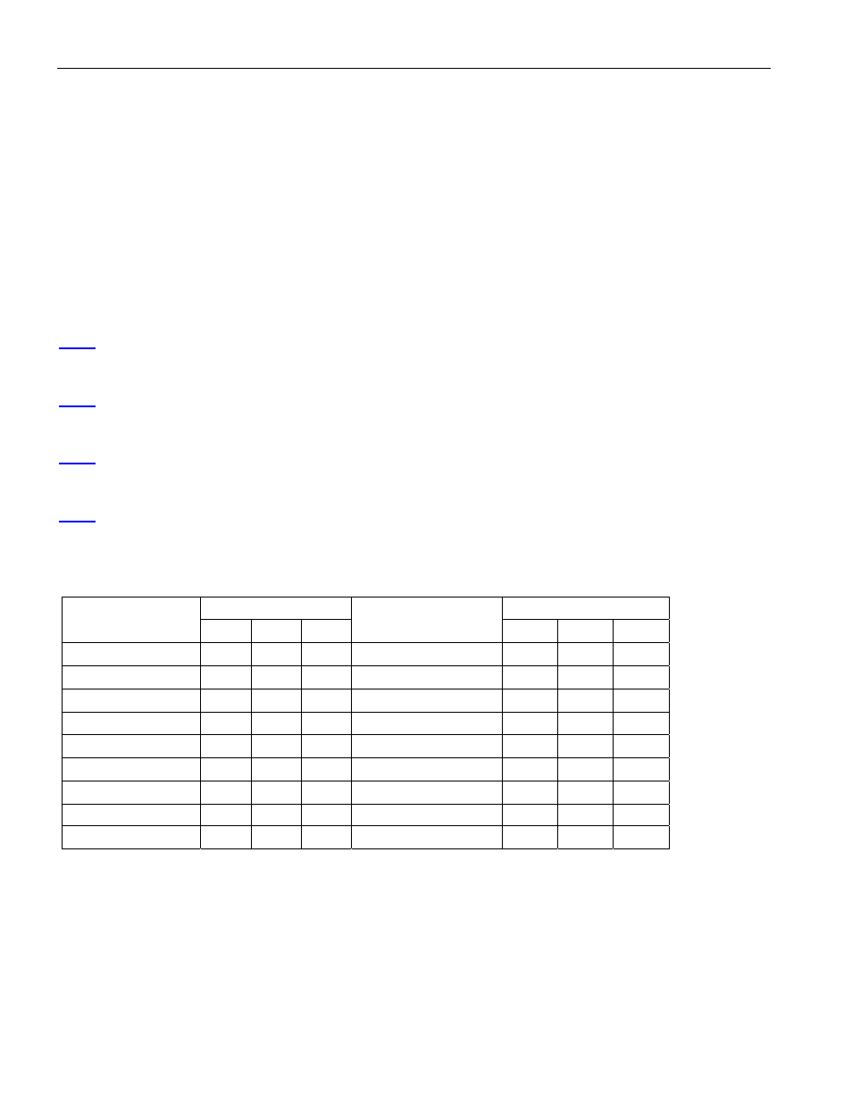
Table 4-I. Instructions That Affect Flag Settings
FLAGS FLAGS
INSTRUCTION
CY OV AC
INSTRUCTION
CY OV AC
ADD
X X X
CLR C
0
ADDC
X X X
CPL C
X
SUBB
X X X
ANL C, bit
X
MUL 0
X
ANL C,
bit
X
DIV 0
X
ORL C, bit
X
DA X
ORL C,
bit
X
RRC X
MOV C, bit
X
RLC X
CJNE X
SETB C
1
Note: X indicates the modification is according to the result of the instruction.