2 ecs wiring connections to xpc port 1a, Gf-122 aerco xpc gateway – AERCO XPC GATEWAY Communications User Manual
Page 71
GF-122 AERCO XPC GATEWAY
71
(a) Connect the “HF” terminal to the “NET +” terminal of Port 2 on the XPC
(b) Connect the “HE” terminal to the “NET -” terminal of Port 2 on the XPC.
2W
4W
232
Net +
Net -
N/C
N/C
Tx +
Tx
Tx -
Rx
DTR
Rx - DCD
SIGNAL
GROUND
Rx +
Port 2
PART OF
EUROTHERM 2408
REAR CONNECTOR
XPC GATEWAY
HD
HE
HF
SHIEL
D
BLUE
(-)
RE
D (+
)
S
H
IE
L
D
TIE TOGETHER WITH
SHIELDS OF OTHER
UNITS
DAISY-CHAIN
TO OTHER UNITS
(
+
TO
+
,
-
TO
-)
BLUE (-)
RED
(+)
R
ED (
+
)
BL
UE (-
)
Figure 5-6. XPC Port 2 Connections to ECS Temperature Controller
3. On the XPC Gateway, check to ensure that DIP switch 3 is set to the OFF position.
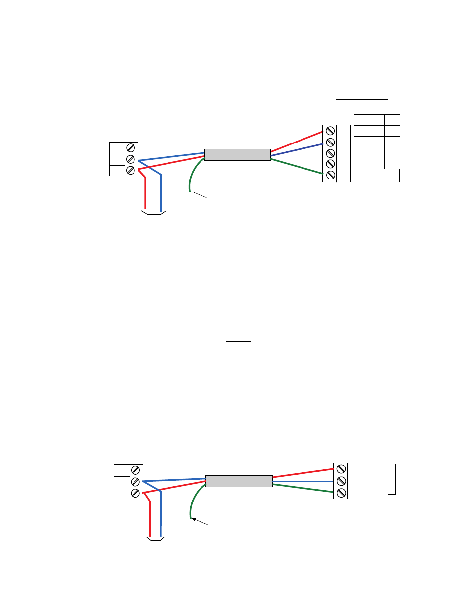
5.2.2 ECS Wiring Connections to XPC Port 1a
When the controlling BAS is connected to Port 2 and is using a LonWorks SLTA or communicating via
BACnet PTP, connect the ECS to XPC Port 1a as follows:
NOTE
The positions of the EIA-232/EIA-485 and 2W/4W jumpers will depend on
the available ports on the controlling BAS being used.
1. Connect ECS terminals HE and HF to XPC Port 1a (Figure 5-7) as follows:
(a) Connect the “HF” terminal to the “NET +” terminal of Port 1a on the XPC
(b) Connect the “HE” terminal to the “NET -” terminal of Port 1a on the XPC.
PART OF
EUROTHERM 2408
REAR CONNECTOR
HD
HE
HF
Net +
Net -
Shield
P
O
RT
1a
XPC GATEWAY
SHIELD
BLUE (-)
RED (
+)
BLUE (-)
RED (
+)
S
H
IE
L
D
TIE TOGETHER WITH
SHIELDS OF OTHER
UNITS
RE
D (+
)
BL
UE (-
)
DAISY-CHAIN
TO OTHER UNITS
(
+
TO
+
,
-
TO
-)