10's 1's, Detail d, Detail f detail e – AERCO XPC GATEWAY Communications User Manual
Page 15: Detail b
GF-122 AERCO XPC GATEWAY
15
8
7
6
5
4
3
2
1
ON
0
5
1
2
3
4
6
7
8
9
0
5
1
2
3
4
6
7
8
9
10's
1's
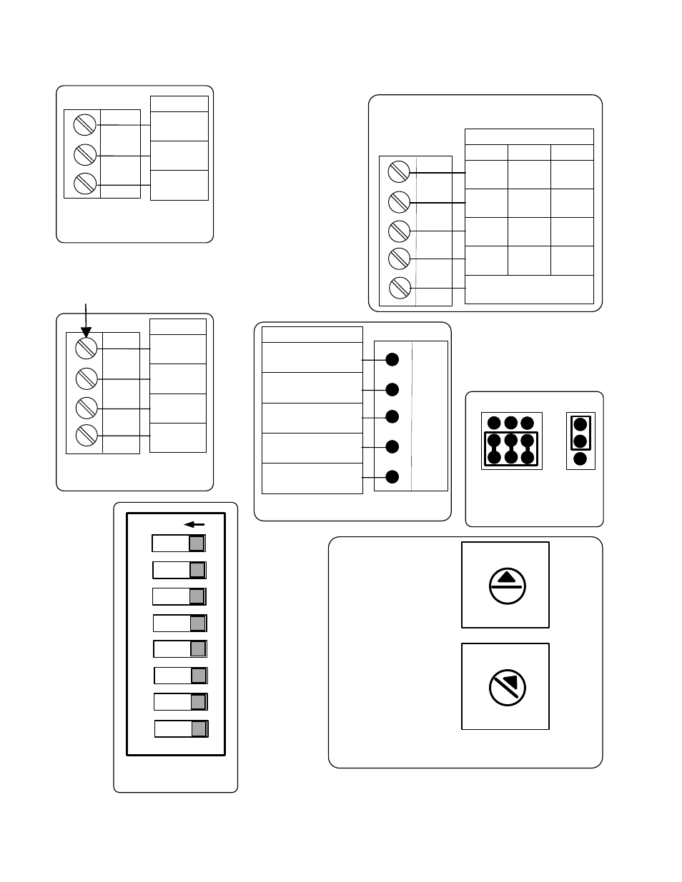
DETAIL F
DETAIL E
EIA-485
EIA-232
2W
4W
DETAIL D
Tx +
Port 2
DETAIL B
2W 4W 232
Net+
Tx
Net - Tx -
Rx
N/C Rx + DTR
N/C Rx - DCD
SIGNAL
GROUND
Net +
Net -
Shield
PORT 1a
DETAIL A
RNET
Gnd
Rnet +
Rnet -
+12V
DETAIL C1
Local
Access
Gnd
Rnet +
Rnet -
+12V
Sense
DETAIL C2
Figure 1-3. XPC Gateway Ports, Jumpers and Switches (Sheet 3 of 3)
Port 2
2W
4W 232
Net+
Tx+
Tx
Net-
Tx-
Rx
N/C
Rx+
DTR
N/C
Rx-
DCD
Signal Ground
Local Access
Gnd
Rnet +
Rnet -
+12V
Sense
RNET
Gnd
Rnet +
Rnet -
+12V
Port 1a
Net +
Net -
Shield
DETAIL B
This BCD switch
determines the 1
decimal position
(1, 2, 3, 4, etc.)
of the address.
This BCD switch
determines the
10 decimal
position (10, 20,
30, 40, etc.) of
the address.
This BCD switch
determines the
10 decimal
position (10, 20,
30, 40, etc.) of
the address.
10’s
1’s
Note for all Pinout
Images:
All connectors on
this page are
shown in the same
orientation as
shown on the
referenced PCB
illustration in
Figure1-3, Sheet 1
of 3.
NOTE: This ground must be
attached to Mounting Panel
(see Figure 1-3, Sht 2 of 3).