1 bms ii set-up for monitoring, 1 bms wiring connections to xpc port 2, Gateway communications manual – AERCO XPC GATEWAY Communications User Manual
Page 56
GATEWAY COMMUNICATIONS MANUAL
56
IS
O
1
2
V
R
X
D
TX
D
2
3
2
IS
O
G
N
D
4
8
5
IS
O
G
N
D
4
8
5
A
4
8
5
B
RS232
RS485
JP5
JP6
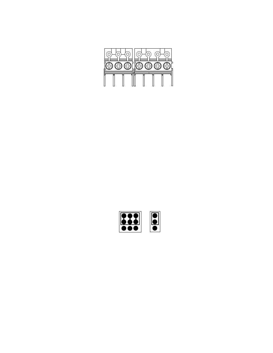
Figure 3-10. BMS II RS232 & RS485 Pinout Assignments
3.3.1 BMS II Set-Up For Monitoring
XPC Gateway Port 2 is normally used to connect to the AERCO BMS, except when the monitoring BAS
is utilizing a LonWorks SLTA, or is communicating via BACnet PTP. In this case, XPC Port 1a must be
used to connect the BMS. Therefore, follow the appropriate wiring instructions in subsection 3.3.1.1 (Port
2) or 3.3.1.2 (Port 1a) as applicable.
3.3.1.1 BMS Wiring Connections to XPC Port 2
When the BAS being used is communicating via BACnet MS/TP, Johnson N2 or LonWorks without an
SLTA, connect to XPC Port 2 as follows:
1. Position the XPC EIA-232/EIA-485 and 2W/4W jumpers to EIA-232 and 2W respectively as shown in
Figure 3-11.
EIA-485
EIA-232
2W
4W
Figure 3-11. Port 2 Jumper Settings
2. Refer to Figures 3-9 and 3-10 to locate the internal RS232 connector inside the wiring area of the
BMS II.
3. At the BMS II internal RS232 connector (JP5), refer to Figure 3-12 and connect the wire leads as
follows:
(a) Connect the TXD terminal of the BMS RS232 connector to Rx terminal on XPC Port 2.
(b) Connect the RXD terminal of the BMS RS232 connector to Tx terminal on XPC Port 2.
(c) Connect the GND terminal of the BMS RS232 connector to SIGNAL GROUND terminal on XPC
Port 2.
(d) Add a jumper between the DTR and DCD terminals on the XPC Port 2. See Figure 1-3 (Detail B).