2 bms ii wiring connections to xpc port 1a, Gf-122 aerco xpc gateway, Figure 3-12. port 2 wiring connections for bms – AERCO XPC GATEWAY Communications User Manual
Page 57
GF-122 AERCO XPC GATEWAY
57
2W
4W
232
Net +
Net -
N/C
N/C
Tx +
Tx
Tx -
Rx
DTR
Rx - DCD
SIGNAL
GROUND
Rx +
Port 2
RED
BLU
E
GREE
N
(GND
)
RED
BLUE
GREEN
(GND
)
XPC GATEWAY
BMS II
JUMPER
232
ISO GND
TXD
RXD
ISO 12V
JP5
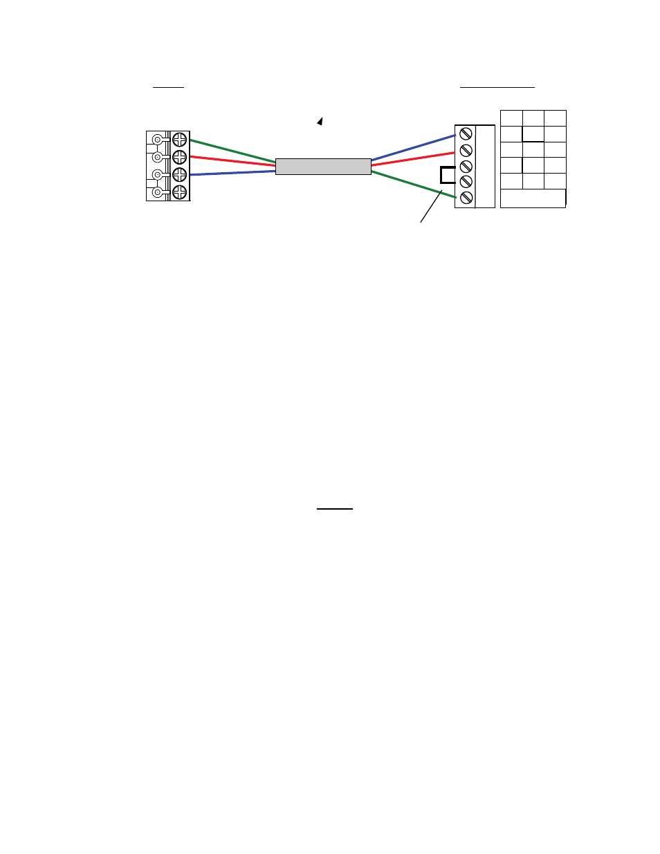
Figure 3-12. Port 2 Wiring Connections for BMS
4. At the XPC Gateway, ensure that DIP switch 3 is set to the OFF (right) position.
3.3.1.2 BMS II Wiring Connections to XPC Port 1a
When the BAS being used is communicating via LonWorks with an SLTA, or BACnet PTP, an RS485-to-
RS232 converter will be required to connect the BMS to Port 1a of the XPC.
1. Refer to Figures 3-9 and 3-10 to locate the internal RS232 connector JP5 inside the wiring area of the
BMS.
2. If the AERCO RS232-to-RS485 Converter (part no. 124942) is used, the RS232 side of the converter
contains a connector that plugs directly into header connector JP5 in the BMS II. However, If a third
party converter is used, connect the RS232 receive (RxD) and transmit (TxD) wire leads to the
internal RS232 connector (JP5) as shown in Figure 3-13. DO NOT connect the wire shield on this
side of the converter.
NOTE
If a third-party RS232-to-RS485 Converter is used, consult the
manufacturer’s instruction manual for signal polarity.
3. At the RS485 side of the converter (Figure 3-13), connect the wire leads as follows:
(a) Connect the TD B (+) terminal to the Net + terminal on XPC Port 1a.
(b) Connect the TD A (-) terminal to the Net - terminal on XPC Port 1a.
(c) Connect the GND terminal to the Shield terminal on XPC Port 1a.