2 c-more wiring connections to xpc port 1a, Gateway communications manual, Figure 2-7. port 2 wiring connections – AERCO XPC GATEWAY Communications User Manual
Page 42: Figure 2-8. port 1a wiring connections
GATEWAY COMMUNICATIONS MANUAL
42
+
G
-
2W
4W
232
Net +
Net -
N/C
N/C
Tx +
Tx
Tx -
Rx
DTR
Rx - DCD
SIGNAL
GROUND
Rx +
Port 2
RED
(+)
BLUE
(-)
SHIEL
D
RED (+)
BLU
E (-)
S
H
IE
L
D
RE
D (+
)
BL
UE (-)
DAISY-CHAIN
TO OTHER UNITS
(
+
TO
+
,
-
TO
-)
TIE TOGETHER WITH
SHIELDS OF OTHER
UNITS
C-MORE I/O BOX
RS
4
85
CO
M
M
XPC GATEWAY
Figure 2-7. Port 2 Wiring Connections
3. At the XPC Gateway, ensure that DIP switch 3 is set to the OFF (right) position.
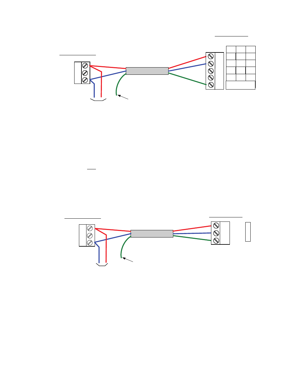
2.6.2 C-More Wiring Connections to XPC Port 1a
Connect to XPC Port 1a as follows:
1. At the I/O Box for the first C-More Controller, connect the RS-485 COMM terminals as follows:
(a) Connect the RS485 + (plus) terminal to the Net + (plus) terminal on XPC Port 1a.
(b) Connect the RS485 – (minus) terminal to the Net – (minus) terminal on XPC Port 1a.
(c) DO NOT connect the wire shield to the Ground (G) terminal at the I/O Box. Connect the wire
shield only to the SIGNAL GROUND terminal at XPC Port 1a. Refer to Figure 2-8.
+
G
-
RED (
+)
BLUE (-)
SHIELD
RED (+)
BLU
E (-)
S
H
IE
L
D
DAISY-CHAIN
TO OTHER UNITS
(
+
TO
+
,
-
TO
-)
TIE TOGETHER WITH
SHIELDS OF OTHER
C-MORE UNITS
Net +
Net -
Shield
P
O
R
T
1a
C-MORE I/O BOX
R
S
485
C
O
M
M
XPC GATEWAY
RED
(+
)
BL
U
E (-)
Figure 2-8. Port 1a Wiring Connections
2. At the XPC Gateway, ensure that DIP switch 3 is set to ON (left) and 4 is set to OFF (right) position.