AERCO C-More Controls Manual June 2010 User Manual
User manual, C-more control panel, C-more controller for benchmark, innovation & kc
C-More Controller for Benchmark, Innovation & KC
USER MANUAL
04/22/14
AERCO International, Inc. • 100 Oritani Dr. • Blauvelt, New York 10913
Page 1 of 162
OMM-0032_0E
Phone: 800-526-0288
GF-112
Applies to:
• Benchmark Boilers
• Innovation Water Heaters
• WHM and BST Systems
• KC Boilers & Water Heaters
Latest Update: 04/22/2014
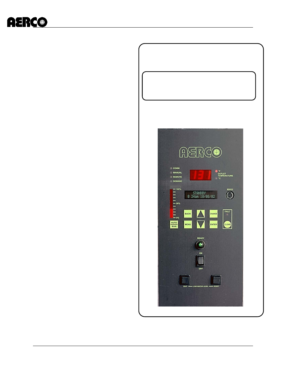
C-More Control Panel
USER MANUAL
Installation, Operation, and Maintenance
C-More Controller Front Panel
This manual is related to the following products:
Table of contents
Document Outline
- Section 1 - GENERAL INFORMATION
- 1.1 INTRODUCTION
- 1.2 SAFETY PRECAUTIONS AND WARNINGS
- 1.3 FEATURES AND BENEFITS
- 1.3.1 System Start Temperature
- 1.3.2 Setpoint Low Limit
- 1.3.3 Setpoint High Limit
- 1.3.4 Temp Hi Limit
- 1.3.5 Max Valve Position
- 1.3.6 Pump Delay Timer
- 1.3.7 Aux Start On Delay
- 1.3.8 Failsafe Mode
- 1.3.9 RS232 Monitoring
- 1.3.10 Password Entry
- 1.3.11 Ignition Retry Functions
- 1.3.12 Fire Rate (FR) Change Rate
- 1.3.13 PID Correction Deadband
- 1.3.14 On/Off Cycling Reduction Functions
- 1.3.15 Demand Offset
- 1.3.16 PID Turn-On Delay
- 1.3.17 Propane/Natural Gas Selection
- 1.3.18 Set Blower Speed During Purge
- 1.3.19 Modbus Network Timeout Control
- 1.3.20 Fault Warning Functions
- 1.3.21 0 – 10V Out Test
- 1.4 CONTROL PANEL DESCRIPTION
- Section 2 - CONTROL PANEL MENU STRUCTURE
- Section 3 - CONTROL PANEL MENU DESCRIPTIONS
- Section 4 - CONTROL PANEL DISPLAY MESSAGES
- Section 5 - INPUT/OUTPUT INTERFACES & OPERATING MODES
- 5.1 INTRODUCTION
- 5.2 I/O INTERFACES
- 5.2.1 Outdoor Sensor In
- 5.2.2 Air Sensor In
- 5.2.3 Analog In
- 5.2.4 B.M.S. (PWM) In
- 5.2.5 Shield
- 5.2.6 mA Out
- 5.2.7 RS485 Comm
- 5.2.8 0 – 10V Output
- 5.2.9 Exhaust Switch In
- 5.2.10 O2 Sensor (O2+, O2-)
- 5.2.11 Flow Meter (Flw+, Flw-)
- 5.2.12 RS-232 Serial (TxD, RxD)
- 5.2.13 Interlocks
- 5.2.14 Fault Relay
- 5.2.15 Auxiliary Relay Contacts
- 5.3 MODES OF OPERATION
- 5.4 START SEQUENCE
- Section 6 - CALIBRATION AND DIAGNOSTIC MENUS
- 6.1 INTRODUCTION
- 6.2 CALIBRATION PROCEDURES
- 6.2.1 Stepper Feedback Calibration
- 6.2.2 PWM In Adjustment.
- 6.2.3 Analog In Adjustment
- 6.2.4 Flow In Adjustment.
- 6.2.5 Supply Gas Pressure In Adjustment.
- 6.2.6 Gas Plate dp In Adjustment
- 6.2.7 mA Out Adjustment
- 6.2.8 A/F Sensitivity
- 6.2.9 Power Reset
- 6.2.10 Water Temp Reset
- 6.2.11 Gas Press Reset
- 6.2.12 Min Off Time
- 6.2.13 Heater Tuning Display
- 6.2.14 Heater Breakpoint Display
- 6.3 DIAGNOSTICS PROCEDURES
- Section 7 - RS232 COMMUNICATION
- Section 8 - WATER HEATER MANAGEMENT (WHM)
- Section 9 - AERCO Boiler Sequencing Technology (BST)
- 9.1 INTRODUCTION
- 9.2 GENERAL DESCRIPTION
- 9.3 BST Modbus Network Wiring
- 9.4 BST Status Displays
- 9.5 BST Menu Structure
- 9.6 BST Setup
- 9.6.1 Option 1 - Constant Setpoint with Direct Wired Header Sensor
- 9.6.2 Option 2 - Constant Setpoint with Modbus Wired Header Sensor
- 9.6.3 Option 3 - Outdoor Reset with Direct Wired Header Sensor & Direct Wired Outdoor Sensor
- 9.6.4 Option 4 - Outdoor Reset with Modbus Header Sensor & Modbus Outdoor Sensor
- 9.6.5 Option 5 - Remote Setpoint with Direct Wired Header Sensor & 4-20ma Setpoint Drive
- 9.6.6 Option 6 - Remote Setpoint with Direct Wired Header Sensor & Modbus Setpoint Drive
- 9.6.7 Option 7 - Remote Setpoint with Modbus Header Sensor & 4-20ma Setpoint Drive
- 9.6.8 Option 8 - Remote Setpoint with Modbus Header Sensor & Modbus Setpoint Drive
- 9.7 TROUBLESHOOTING
- APPENDIX A: ProtoNode SSD Setup for BST and HST Applications
- APPENDIX B: MODbus Temperature Transmitter Installation
- APPENDIX C: INDOOR/OUTDOOR RESET RATIO CHARTS
- APPENDIX D: C-MORE CONTROL PANEL VIEWS
- APPENDIX E: TEMPERATURE SENSOR RESISTANCE-VOLTAGE CHART
- APPENDIX F: C-MORE CONTROL PANEL DIP SWITCH SETTINGS