1 bms set-up for monitoring, Gateway communications manual, Figure 3-2. partial front view with cover removed – AERCO XPC GATEWAY Communications User Manual
Page 48: View a – a, Db9 (female), Jp 11, Rs485 to blrs
GATEWAY COMMUNICATIONS MANUAL
48
L
N
AU
X
FL
T
AL
AR
M
SYS ST
AR
T
SE
T
BAC
K
IN
T2
IN
T1
4-2
0
M
A
16
15
14
13
12
11
-1
0
+9
SH
IEL
D
8
R
EF
TEM
P
H
D
R
TEM
P
SE
N
SH
IEL
D
3
4
5
6
7
O
U
T
AI
R
SEN
1
2
BL
R 1
+1
-2
+3
-4
+5
-6
+7
-8
+9
-1
0
+1
1
-1
2
+1
3
-1
4
+1
5
-1
6
BL
R 2
BL
R 3
BL
R 4
BL
R 5
BL
R 6
BL
R 7
BL
R 8
85-265 VAC
JP
4
JP3
JP
2
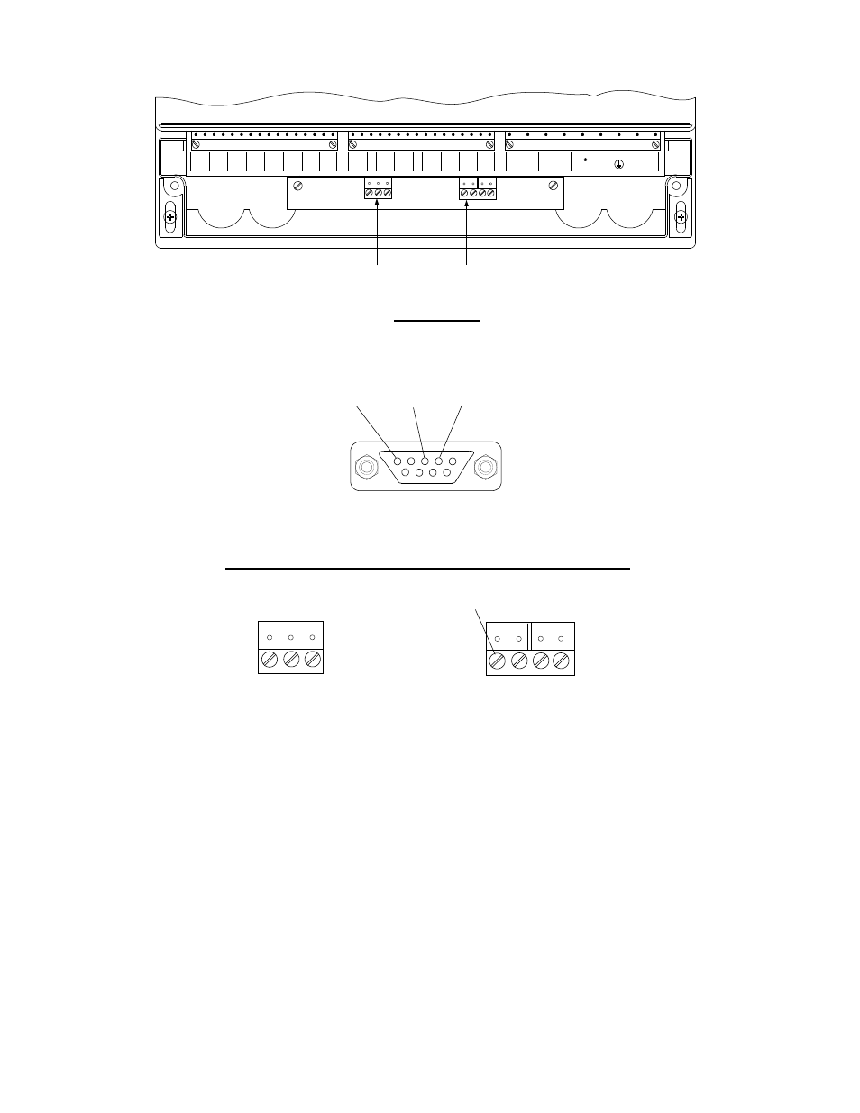
+(B) -(A) SHLD
RXD TXD GND
RS485
TO BLRS
RS232
JP
11
JP
12
VIEW A – A
RS485
CONNECTOR
RS232
CONNECTOR
Figure 3-2. Partial Front View With Cover Removed
DB9 (FEMALE)
PIN 5
GND
PIN 3
TxD
PIN 2
RxD
5
1
9
6
RXD TXD GND
RS232
JP
12
+(B) -(A)
SHLD
RS485
TO BLRS
JP
11
NOT
USED
EXTERNAL RS232 PORT
INTERNAL RS485 & RS232 PORTS
RS485 PORT
RS232 PORT
Figure 3-3. BMS RS232 & RS485 Connectors
The following subsections provide the procedures necessary connect the BMS to the XPC Gateway and
configure it for monitoring or remote setpoint control by a BAS.
3.2.1 BMS Set-Up For Monitoring
XPC Gateway Port 2 is normally used to connect to the AERCO BMS, except when the monitoring BAS
is utilizing a LonWorks SLTA, or is communicating via BACnet PTP. In this case, XPC Port 1a must be
used to connect the BMS. Therefore, follow the appropriate wiring instructions in subsection 3.2.1.1 (Port
2) or 3.2.1.2 (Port 1a) as applicable.