2 bcm wiring connections to xpc port 1a, Gateway communications manual, Figure 4-3. port 2 jumper settings – AERCO XPC GATEWAY Communications User Manual
Page 66: Figure 4-4. xpc port 2 connections to bcm
GATEWAY COMMUNICATIONS MANUAL
66
Figure 4-3. Port 2 Jumper Settings
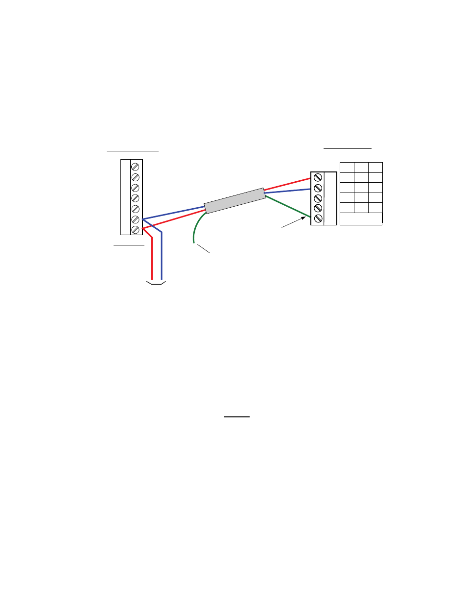
2. Connect BCM terminals Y2-1 and Y2-2 to XPC Port 2 (Figure 4-4) as follows:
(a) Connect the Y2-1 (Modbus B +) terminal to the “NET +” terminal of Port 2 on the XPC
(b) Connect the Y2-2 (Modbus A -) terminal to the “NET -” terminal of Port 2 on the XPC.
2
1
TERMINATE SHIELD
AT XPC ONLY
BCM
CONNECTOR Y2
FIRST UNIT
S
H
IE
L
D
TIE TOGETHER WITH
SHIELDS OF OTHER
C-MORE UNITS
RED
(+)
BLUE
(-)
RED
(+)
BLUE (-)
5
4
6
3
7
2W
4W
232
Net +
Net -
N/C
N/C
Tx +
Tx
Tx -
Rx
DTR
Rx - DCD
SIGNAL
GROUND
Rx +
Port 2
XPC GATEWAY
DAISY-CHAIN
TO OTHER UNITS
(+ TO +, - TO -)
RED
(+
)
B
LUE
(-)
Figure 4-4. XPC Port 2 Connections to BCM
3. On the XPC Gateway, check to ensure that DIP switch 3 is set to the OFF position.
4.2.2 BCM Wiring Connections to XPC Port 1a
When the controlling BAS is connected to Port 2 and is using a LonWorks SLTA or communicating via
BACnet PTP, connect the BCM to XPC Port 1a as follows:
NOTE
The positions of the EIA-232/EIA-485 and 2W/4W jumpers will depend on
the available ports on the controlling BAS being used.
1. Connect BCM terminals Y2-1 and Y2-2 to XPC Port 1a (Figure 4-5) as follows:
(a) Connect the Y2-1 (Modbus B +) terminal to the “NET +” terminal of Port 1a on the XPC
(b) Connect the Y2-2 (Modbus A -) terminal to the “NET -” terminal of Port 1a on the XPC.