Gateway communications manual – AERCO XPC GATEWAY Communications User Manual
Page 14
GATEWAY COMMUNICATIONS MANUAL
14
+12V
RNET-
RNET+
GND
COM
NET-
RX
TX
FORMAT
POWER
NET+
CMNET
ONE's
ERR
RUN
OPTIONS
TEN's
BATT
24VAC
GND
POWER
485
232
LN-
/S
+12
GND
LN+
2W
RX
TX
4W
BT485
Net +
Net -
Shield
P
o
rt
1
a
Tx1
Rx1
P
o
rt
1
b
Port 2
4w
2w
Gnd
+12V
Gnd
Rnet+
Sense
Rnet +
Rnet -
R
n
e
t
Rnet-
+12V
Local
Access
10's
1's
0
1
3
4
5
2
7
8
9
6
0
1
3
4
5
2
7
8
9
6
4
3
2
1
On
5
6
7
8
Run
Error
Power
Format
Gnd
Hot
EIA- 232
EIA- 485
Baud
EIA485
19.2k
38.4k 76.8k
BMS
Port 2
ARC156
Port 1
9600
BMS
Switches
( 0 = off , 1 = on)
MSTP (m)
MSTP (s)
PTP
8 7 6 5
Protocol
0 0 0 0
0 0 0 1
0 0 1 0
B
A
C
n
e
t
BMS
Port 1
TYPE: 002106
Enclosed Energy Management Equipment
Made in USA
®
24V ac
2w
4w
Tx+
n/c
n/c
Net+
Rx+
Rx-
Tx-
Net-
232
Tx
DTR
DCD
Rx
Signal Ground
+
-
Batt
CR
2032
BT485
Lon SLTA
1 1 0 1
Lon PlugIn
Ethernet
1 1 1 1
1 1 1 0
N2
Modbus
®
®
0 1 1
0 1 0 0
0
Tx2
Rx2
E 143900
88FO
R
Class 2 , 24Vac
Conductors Only
Use Copper
50-60Hz, 10VA, 0.42A
®
XPC
PORT 1a
( DETAIL “A”)
PORT 2
( DETAIL “B”)
RNET
(DETAIL “C1”)
PORT 1b
JUMPERS
( DETAIL “D”)
0
5
1
2
3
4
6
7
8
9
0
5
1
2
3
4
6
7
8
9
8
7
6
5
4
3
2
1
ON
INPUT
POWER
( 24 VAC)
DIP
SWITCHES
( DETAIL “E”)
ADDRESS
SELECT
SWITCHES
( DETAIL “F”)
BATTERY
(3V)
LOCAL
ACCESS
PORT
(DETAIL “C2” )
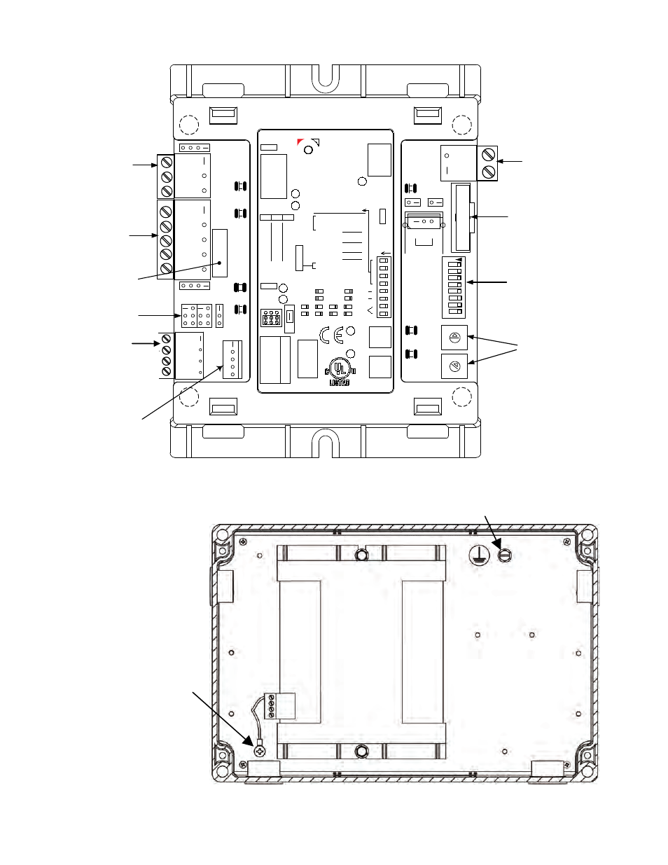
Figure 1-3. XPC Gateway Ports, Jumpers and Switches (Sheet 1 of 3)
Figure 1-3. XPC Gateway Chassis Ground Locations (Sheet 2 of 3)
NOTE: Ground
is attached to
Mounting Panel
(see Sht 2 of 3).
RNET
(DETAIL “C1”)
Ground connection lug for
RNET connector.
DO NOT
REMOVE. This ground
MUST be connected when
power is applied to the
Gateway Controller.
Earth ground connection lug. Connect
earth ground here.