3 configuring the bms ii, Gateway communications manual – AERCO XPC GATEWAY Communications User Manual
Page 58
GATEWAY COMMUNICATIONS MANUAL
58
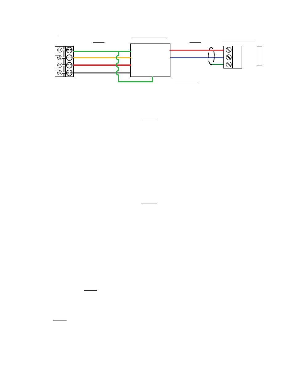
Net +
Net -
Shield
P
O
RT
1a
XPC GATEWAY
RS232-TO-RS485
CONVERTER
TXD
RXD
GND
GND
B (+)
A
(-)
RED (+)
BLUE (-)
GREEN (GND)
RED
ORANGE
IMPORTANT
CHECK INPUT & OUTPUT
POLARITY ON CONVERTER
BEING USED
BMS
RS232
RS485
232
ISO GND
TXD
RXD
ISO 12V
JP5
+12V
GND
Figure 3-13. Port 1a Wiring Connections for BMS
NOTE
A BMS II option is available with a built-in RS485-to-232 Converter (part no,
124943).
4. On the right side of the XPC Gateway Module, check to ensure that DIP switches 3 and 4 are set to
the ON (left) position.
3.3.1.3 Configuring the BMS II
Once the BMS II has been wired to the Gateway as described in subsection 3.3.1.1 or 3.3.1.2, turn on
power to the BMS II and perform the following configuration settings:
NOTE
Refer to AERCO Instruction Manual GF-124 for additional information on
BMS II keypad functions and displays.
1. Press the
MENU key and go to the SETUP MENU.
2. P
ress the ▲ arrow key. ENTER PASSWORD will be displayed requesting the valid password to be
entered.
3.
Using the ▲ and ▼ arrow keys, enter the valid level 1 password (159) and then press the
ENTER
key. LEVEL 1 PASSWORD will be displayed.
4. Press the
MENU key again. RS232 MENU is displayed.
5.
Press the ▲ arrow key. RS232 MODE appears in the first line of the display.
6. If MODBUS SLAVE is not displayed in the second line of the display, press the
CHANGE key and
toggle the display to MODBUS SLAVE. Press the
ENTER key to store the setting.
7. While still in the RS232 MENU
, press the ▲ arrow key. RS232 BAUDRATE is displayed in the first
line of the display.
8. If 9600 is not displayed in the second line of the display, press the
CHANGE key and select 9600
using the ▲ or ▼ arrow key. Press the
ENTER key to store the 9600 Baud Rate.