1 input power connection, 2 protocol and baud rate select, Gateway communications manual – AERCO XPC GATEWAY Communications User Manual
Page 16
GATEWAY COMMUNICATIONS MANUAL
16
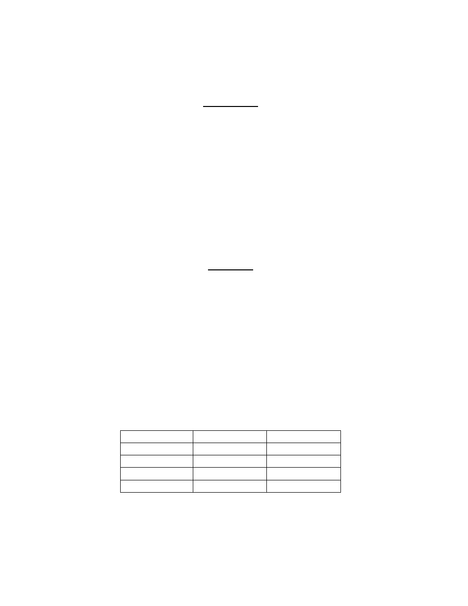
1.6 POWER INPUT, PROTOCOL SELECTION & GATEWAY ADDRESSING
The Gateway input power connections, protocol selection, and Gateway addressing are
accomplished utilizing the connector and switches on the right side of the XPC Gateway as shown in
Figure 1-3. The following subsections provide brief descriptions of the ports and jumpers provided.
IMPORTANT
It is imperative that the XPC Gateway be powered by an isolated 24
VAC power supply which is dedicated only for use by the XPC
Gateway. Failure to observe this precaution will result in improper
Gateway operation.
1.6.1 Input Power Connection
The Gateway is powered by 24 VAC (Class 2), 50/60 Hz, 20 VA. The input power connector is
located on the upper right side of the Gateway (Figure 1-3, Sheet 1 of 3).
When connecting the power source, an earth ground MUST be connected to the ground screw on the
mounting panel. See Figure 1-3, Sheet 2 of 3.
In addition, a 3 volt lithium battery (CR2032) is installed below the AC power connector. This battery
is used to retain the current monitoring/control data stored in volatile memory.
WARNING
Do not remove the battery when the power is off. Doing so may erase
some recorded data as well as programming, especially on older
models not utilizing non-volatile memory. The battery maintains the
integrity of the data and coding contained in memory whenever the
supply voltage is not present.
1.6.2 Protocol and Baud Rate Select
Protocol and baud rate selection are accomplished using the 8 DIP switches shown in Figure 1-3,
Detail “E”. The DIP switches can be set to the ON (left) or OFF (right) position. The functions and
settings for each of these switches are listed in the Tables 1 and 2 which follow.
Table 1 Baud Rate Select Switches
BAUD Rate
DIP Switch 1
DIP Switch 2
9600
OFF
OFF
19.2 K
OFF
ON
38.4 K
ON
OFF
76.8 K
ON
ON
• DIP Switch 3 selects whether XPC Port 1 or Port 2 will be connected to the BAS used with the
Gateway. When DIP Switch 3 is OFF, Port 1 is connected to the BAS. When set to ON, Port 2 is
connected to the BAS. The other port will be used for connection of AERCO equipment.
• DIP Switch 4 will normally be set to ON for RS485 communication. It should only be set to OFF if
the BAS Port is 1 and the BAS is communicating BACnet using the ARC156 method.