2 bas terminating resistor and bias, 1 c-more wiring connections to xpc port 2, Gf-122 aerco xpc gateway – AERCO XPC GATEWAY Communications User Manual
Page 41
GF-122 AERCO XPC GATEWAY
41
2.5.2 BAS Terminating Resistor and Bias
Refer to the BAS manufacturer’s Technical Manual and follow their recommended guidelines for
termination resistors and bias.
NOTE
DO NOT connect C-More boilers to the XPC Gateway as described in
subsection 2.6 if the boilers are being controlled by a BMS Master on the
Modbus network. Refer to Section 3, subsection 3.3 for wiring and set-up
instructions when controlled by the BMS.
2.6 C-MORE CONTROLLER WIRING CONNECTIONS TO AERCO XPC GATEWAY
XPC Port 2 is normally used to connect to AERCO equipment, except when the controlling BAS is
utilizing a LonWorks SLTA module, or communicating via BACnet PTP. In this case, Port 1a of the XPC
must be used to connect AERCO equipment. Therefore, follow the appropriate wiring instructions in
subsection 2.6.1 (Port 2) or 2.6.2 (Port 1a) as applicable.
2.6.1 C-More Wiring Connections to XPC Port 2
When the controlling BAS is utilizing BACnet MS/TP, Johnson N2 or LonWorks protocol without an
SLTA, use XPC Port 2 as follows:
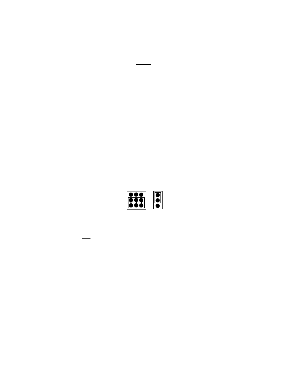
1. Position the EIA-232/EIA-485 and 2W/4W jumpers to EIA-485 and 2W respectively as shown in
Figure 2-6.
EIA-485
EIA-232
2W
4W
Figure 2-6. Port 2 Jumper Settings
2. At the I/O Box for the first C-More Controller, connect the RS-485 COMM terminals as follows:
(a) Connect the RS485 COMM + (plus) terminal to the Net + (plus) terminal on XPC Port 2.
(b) Connect the RS485 COMM – (minus) terminal to the Net – (minus) terminal on XPC Port 2.
(c) DO NOT connect the wire shield to the Ground (G) terminal at the I/O Box. Connect the wire
shield only to the SIGNAL GROUND terminal at XPC Port 2. Refer to Figure 2-7.