2 ecs wiring connections to aerco xpc gateway, 1 ecs wiring connections to xpc port 2, Gateway communications manual – AERCO XPC GATEWAY Communications User Manual
Page 70: Figure 5-5. port 2 jumper settings
GATEWAY COMMUNICATIONS MANUAL
70
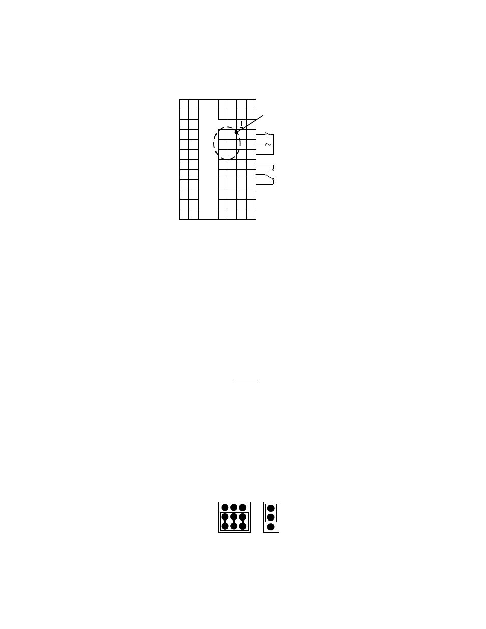
4. Refer to the Temperature Controller RS485 terminal connections shown in Figure 5-4.
1A
HA
1B
HB
1C
HC
2A
2B
1D
HE
HF
HD
3B
3D
3C
2D
3A
2C
JD
JF
JE
JB
JC
JA
LA
LB
LC
AA
AB
AC
VI
V+
V-
In1
In2
C
2408 CONTROLLER
L
N
RS485
MODBUS
CONNECTIONS
Figure 5-4. Temperature Controller (Eurotherm 2408) Terminal Connections
5. Proceed to subsection 5.2 and wire the ECS to the appropriate XPC port connector for the application
being used.
5.2 ECS WIRING CONNECTIONS TO AERCO XPC GATEWAY
XPC Port 2 is normally used to connect to AERCO equipment, except when the controlling BAS is
utilizing a LonWorks SLTA module, or communicating via BACnet PTP. In this case, Port 1a of the XPC
must be used to connect AERCO equipment. Therefore, follow the appropriate wiring instructions in
subsection 5.2.1 (Port 2) or 5.2.2 (Port 1a) as applicable.
NOTE
Do not connect the termination resistors sent with the ECS. This will
impede communication.
5.2.1 ECS Wiring Connections to XPC Port 2
When the controlling BAS is utilizing BACnet MS/TP, Johnson N2 or LonWorks protocol without an
SLTA, use XPC Port 2 as follows:
1. Position the EIA-232/EIA-485 and 2W/4W jumpers to EIA-485 and 2W respectively as shown in
Figure 5-5.
EIA-485
EIA-232
2W
4W
Figure 5-5. Port 2 Jumper Settings
2. Connect ECS terminals HE and HF to XPC Port 2 (Figure 5-6) as follows: