4 c-more controller modbus communication interface, Gf-122 aerco xpc gateway – AERCO XPC GATEWAY Communications User Manual
Page 35
GF-122 AERCO XPC GATEWAY
35
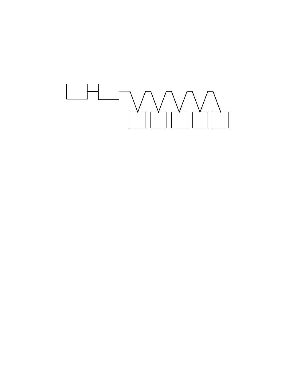
Modbus RS485 devices should be wired in a “Daisy-Chain” configuration similar to the example shown
Figure 2-1. DO NOT wire the units in a “Star” configuration where all devices are connected to a central
point (node).
BAS
MASTER
SLAVE
#1
SLAVE
#2
SLAVE
#3
SLAVE
#4
SLAVE
#5
XPC
GATEWAY
Figure 2-1. Typical Daisy-Chain Modbus/RS485 Network
Subsections 2.4 through 2.7 provide the set-up and programming instructions necessary to implement a
communications network utilizing the AERCO XPC and C-More Controller Slaves controlled by a Master
BAS.
2.4 C-MORE CONTROLLER MODBUS COMMUNICATION INTERFACE
The RS485 Modbus communication (COMM) connections for C-More Controller slaves are made in the
Input/Output (I/O) Box shown in Figure 2-2.
Identical I/O Boxes are used for Benchmark Boilers and
KC1000 Boilers or Water Heaters. The connections are made at the
RS485 COMM terminals labeled +
(plus), and
– (minus). Observe the NOTE in Figure 2-2 and never terminate wire shields to the G
(Ground) terminal.