AERCO Belimo GMX24-MFT Actuator User Manual
AERCO Equipment
800-543-9038 USA
866-805-7089 CANADA
203-791-8396 LATIN AMERICA
362
Installation and Operation
Non-Spring Return
General Information
Preliminary Steps
1. Belimo actuators with NEMA 1 or NEMA 2 ratings should be mounted indoors in
a dry, relatively clean environment free from corrosive fumes. If the actuator is
mounted outdoors, a protective enclosure must be used to shield the actuator.
2. For new construction work, order dampers with extended shafts. Instruct the
installing contractor to allow space for mounting the Belimo actuator on the shaft.
For replacement of existing gear train actuators, there are two options:
A. From a performance standpoint, it is best to mount the actuator directly onto the
damper shaft.
B. If the damper shaft is not accessible, mount the non-spring return actuator with
a ZG-NMA or ZG-GMA crank arm kit, and a mounting bracket (ZG-100, ZG-101,
ZG-103, ZG-104)
Determining Torque Loading and Actuator Sizing
Damper torque loadings, used in selecting the correct size actuator, should be pro-
vided by the damper manufacturer. If this information is not available, the following
general selection guidelines can be used.
Damper Type
Torque Loading
Opposed blade, without edge seals, for
non-tight close-off applications
3 in-lb/sq. ft.
Parallel blade, without edge seals, for
non-tight close-off applications
4 in-lb/sq. ft.
Opposed blade, with edge seals, for tight
close-off applications
5 in-lb/sq. ft.
Parallel blade, with edge seals, for tight
close-off applications
7 in-lb/sq. ft.
The above torque loadings will work for most applications under 2 in. w.g. static
pressure or 1000 FPM face velocity. For applications between this criteria and 3 in.
w.g. or 2500 FPM, the torque loading should be increased by a multiplier of 1.5. If
the application calls for higher criteria up to 4 in. w.g. or 3000 FPM, use a multiplier
of 2.0.
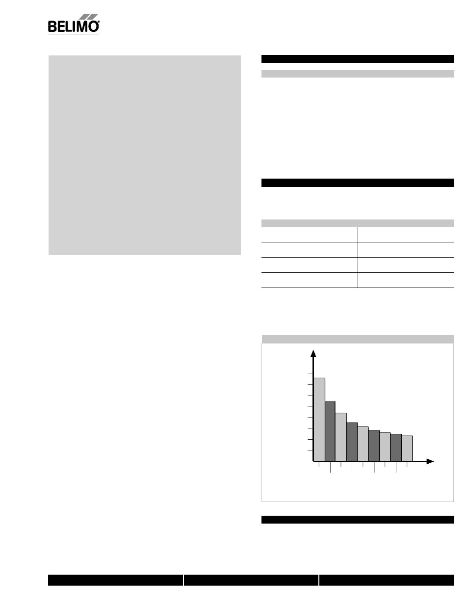
Torque Loading Chart
140
120
100
80
60
40
20
0
2
3
4
6
8
10
5
7
9
Damper
Area (sq. ft.)
Torque Loading (in-lb/ sq. ft.)
Multiple Actuator Mounting
If more torque is required than one GM can provide, GM24B, GMB24-SR or GMX24-
MFT may be installed on the same shaft.
Table of Contents
PAGE
General Mounting
Standard .............................................................270
Reversible
Clamp ................................................271
Linear .................................................................272
Rotary .................................................................273
Retrofit Brackets .................................................275
Operation
Electrical .............................................................276
Mechanical .........................................................277
Wiring
General ...............................................................278
Accessories ........................................................279
Startup and Checkout ..............................................282
M40024 - 05/10 - Sub
ject to chan
g
e.
© Belimo
Aircontrols
(USA
), Inc.